95
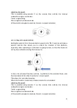
To use this function in the best way, it is advisable to control both Joysticks in
the desired direction first) with selector 9 on hare) and then move selector 8
from DM to DC-S.
At this point it is possible to release the left joystick and to keep holding only
the right one. The machine will continue to move straight at maximum speed.
Warning: It is not possible to perform the reverse procedure; once the machine
travels in DC-S it cannot go back to DM, not even if selector 8 is moved.
It is only possible to stop the machine completely by releasing the right joystick.
Warning: When the joystick is released, the machine will not stop immediately
bit there is a deceleration ramp. The space travelled before it stops can even be
of 50 cm.
Warning: When the joystick is released, the machine will not stop immediately
bit there is a deceleration ramp. The space travelled before it stops can even be
of 50 cm.
4.2.4.4
Travel mode with the work platform above the transport height
With the platform raised above the transport height, the maximum travel speed
is automatically limited to a maximum value of 0.4Km/h.
All the functions remain the same as with the platform in the transport
configuration.
Only the Direct-Control System (DC-S) function is different; in this case neither
the capacity variation of the hydraulic engines nor the booster will be activated.
Summary of Contents for 1090 EVO
Page 7: ...7...
Page 22: ...22...
Page 23: ...23...
Page 49: ...49 37 Combustion engine 38 Fuel tank 39 Bi levelling chassis 37 38...
Page 78: ...78...
Page 80: ...80...
Page 122: ...122 In this configuration the oil level must be as shown in the figure below A 60mm...
Page 144: ...144...
Page 145: ...145...
Page 146: ...146...
Page 147: ...147...
Page 148: ...148...
Page 149: ...149...
Page 150: ...150...
Page 151: ...151...
Page 152: ...152...
Page 161: ...161 8 ATTACHMENTS 8 1 Declaration of conformity...
Page 163: ...163 MANDATORY ROUTINE INSPECTIONS Date Observations Seal Signature...
Page 177: ...177 8 4 Hydraulic diagram See attachment 8 5 Wiring diagram See attachment...


