PAGE
68
3.4
Platform operation safety devices
Attention: Periodically verify that the safety devices are operating correctly.
During work, the operator must be able to assess, recognize and avoid all
dangers and must immediately inform the persons in charge of any faults in the
safety devices so that they can be inspected and restored to their original
conditions of safety and reliability
DO NOT TAMPER WITH AND DO NOT CHANGE THE CALIBRATION OF ANY OF
THE COMPONENTS OF THE ELECTRICAL AND HYDRAULIC SYSTEM.
The platform comprises a complete set of safety devices.
3.4.1
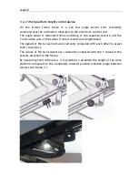
Main frame inclination control device
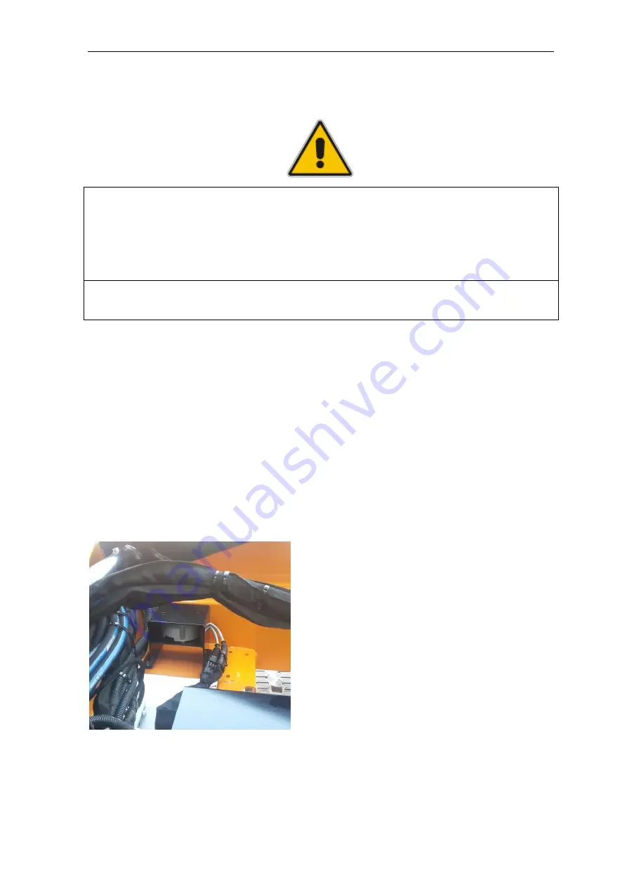
On the machine Frame there is a Can Bus angle sensor that constantly
communicates the inclination measured to the electronic control unit.
The angle sensor is redundant (thus consisting of two separate sensors) and the
X and Y inclination axes of the machine are monitored (lateral and longitudinal)
The signals of the two sensors are constantly compared with each other to assess
their consistency.
The device is placed under a cover positioned inside the frame.
Summary of Contents for 1470-HE EVO
Page 7: ...PAGE 7...
Page 12: ...PAGE 12 Work area on tracks Travel not allowed Maximum inclination allowed 2 5020 5490 7500...
Page 27: ...PAGE 27...
Page 28: ...PAGE 28...
Page 34: ...PAGE 34 Warning Do not tighten the fixing belts too much so as not to damage the eye bolts...
Page 50: ...PAGE 50 8 Extendible basket pedal...
Page 57: ...PAGE 57 38 Chassis and stabilisers...
Page 74: ...PAGE 74...
Page 76: ...PAGE 76...
Page 77: ...PAGE 77...
Page 80: ...PAGE 80...
Page 138: ...PAGE 138...
Page 160: ...PAGE 160...
Page 161: ...PAGE 161...
Page 162: ...PAGE 162...
Page 163: ...PAGE 163...
Page 164: ...PAGE 164...
Page 165: ...PAGE 165...
Page 166: ...PAGE 166...
Page 167: ...PAGE 167...
Page 168: ...PAGE 168...
Page 178: ...PAGE 178 MANDATORY ROUTINE INSPECTIONS Date Observations Seal Signature...
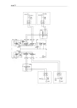
Page 191: ...PAGE 191 8 4 Hydraulic diagram See attachment 8 5 Wiring diagram See attachment...

