background image

PAGE

100 


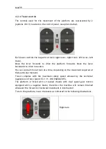
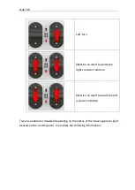
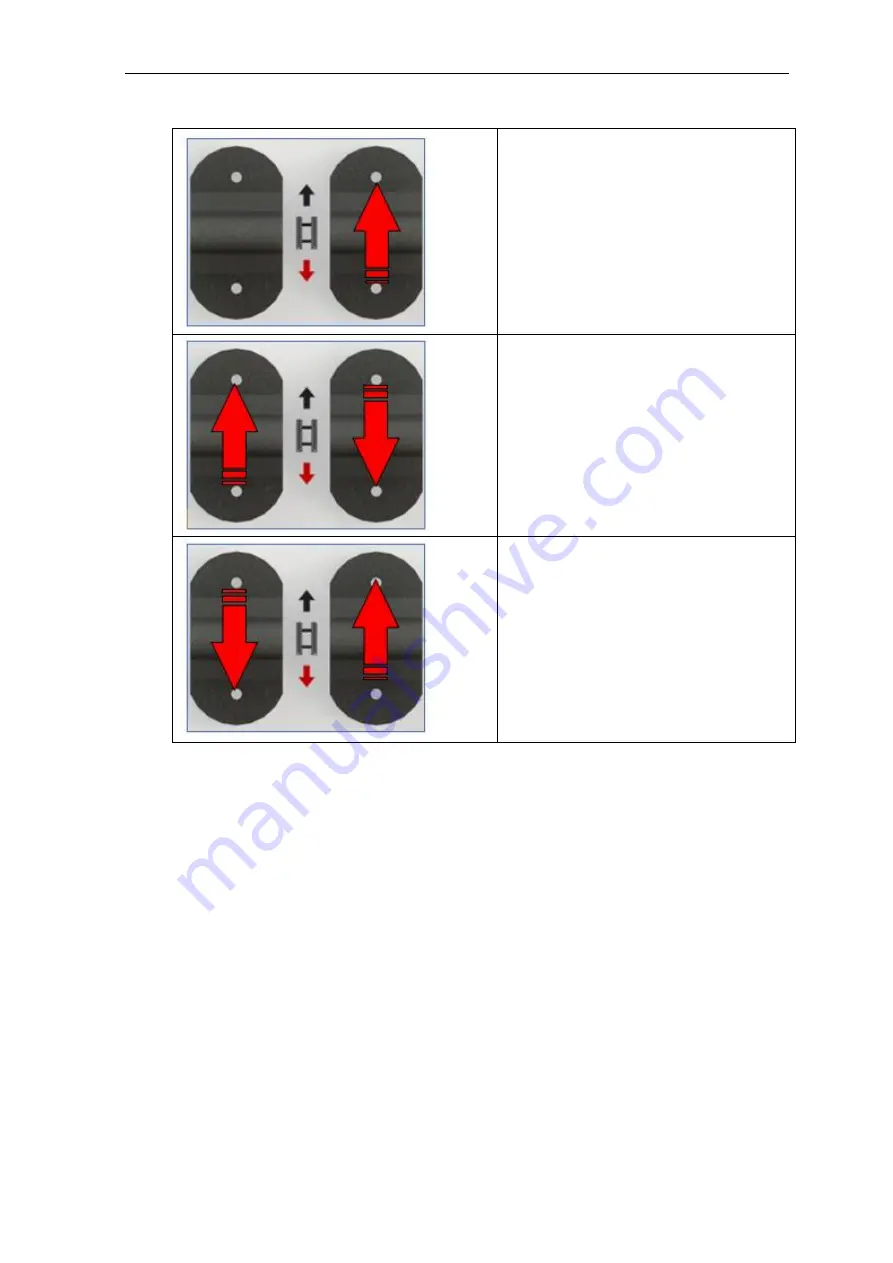
Left turn 


Rotation on itself towards the 

right (counter-rotation) 


Rotation on itself towards the left 

(counter-rotation) 


Travel is enabled or disabled depending on the status of the travel approval light 
located on the control panel. It provides the following information: 


Summary of Contents for 1470-HE EVO

Page 1: ...NA1470 HEEVO Translationoforiginalinstructions Prior to commissioning the machine read carefully this Use and Maintenance Manual Note table of contents at the end of the manual Edition Date 00 04 07 2...

Page 2: ...Athena 1470 HE EVO Note Some of the photos and illustrations may not refer specifically to the version of the machine in your possession but provide indications concerning the purpose for which they...

Page 3: ...h the technical and safety specifications of the machine to which the manual refers The manufacturer declines all liability for direct or indirect damage to persons things or animals deriving from use...

Page 4: ...ype 3 point 1 4 EN 280 Meanings GROUP A Mobile elevating work platforms where the vertical projection of the centre of the platform area in all platform configurations at the maximum chassis inclinati...

Page 5: ...LIC PRESSURE ELEVATING BATTERY VOLTAGE MAX ALLOWABLE INCLINATION OF CHASSIS THIS MACHINE COMPLIES WITH STATE DESIGN REGISTRATION NUMBERS NSW VIC SA QLD Designed and Manufactured by Distributed by Alma...

Page 6: ...PAGE 6 1 6 Performance Below are the configurations that the mobile elevating work platform can have during operation and transport...

Page 7: ...PAGE 7...

Page 8: ...nimum height A7 mt 2 80 Width of work platform A8 mt 1 14 Chassis width A9 mt 1 15 Machine length With stabilisers in line A10 mt 3 35 Minimum height transport only Railings closed A11 mt 2 15 Length...

Page 9: ...PAGE 9 Work area on stabilisers in wide position Maximum inclination allowed 0 5 B9 B10 B8 B12 B11 B4 B6 B7 B3 B5 B5 B2 B1...

Page 10: ...h B4 mt 5 02 Useful work distance in width B5 mm 280 Useful work distance in length B6 mm 140 Useful work distance in length B7 mt 1 70 Distance between the stabilisers in width B8 mt 1 4 Maximum heig...

Page 11: ...n Maximum inclination allowed 0 5 7160 9160 1000 1130 3230 3480 11 10 2 4 2080 5020 4000 1370 10 1680 460 460 Warning It is sufficient to position a single stabiliser in the narrow position to have th...

Page 12: ...PAGE 12 Work area on tracks Travel not allowed Maximum inclination allowed 2 5020 5490 7500...

Page 13: ...300 Number of operators on work platform 2 Lifting time with 300Kg on the platform s 60 Lowering time s 60 Hydraulic side shift pressure Bar 195 5 Hydraulic lifting pressure Bar 195 5 Climb angle 25...

Page 14: ...le body vibration platform measured on flat ground m s2 0 52 0 10 Vibrations transmitted to hand arm system operator hand rest m s2 0 59 0 12 Max Manual Force daN 40 values refer to platform raised op...

Page 15: ...eight 60 kg Type of engine 4 TIMES LIQUID COOLING DIESEL Swept volume 599 cm3 Net power 12 5 kW 3600 rpm Net torque 38 Nm 2500 rpm Q ty engine oil 3 Lt Fuel tank capacity 30 Lt Engine specifications E...

Page 16: ...anti shearing function has been used as provided for in Point 5 4 3 of UNI EN 280 2015 with permanent warning signs 1 8 Warranty ALMAC S r l guarantees the equipment it manufactures and undertakes to...

Page 17: ...formation is given on the identification plate of the equipment 1 9 Assistance As far as the optimum use of the machine and extraordinary maintenance are concerned this manual does not replace the exp...

Page 18: ...he serial number of the machine given on the relative identification plate when requesting a new copy of the manual The manufacturer undertakes to provide a new copy Note When selling used equipment t...

Page 19: ...sider the following 2 two persons each weighing 80 kg 140 kg of equipment An electronic control system prevents the work platform from lifting to any position when the load exceeds approx 20 of the ra...

Page 20: ...RBIDDEN to use the machine to tow other equipment or vehicles Warning the machine is designed to be driven around within public or private areas It is not designed for road circulation Warning The mac...

Page 21: ...for EMERGENCY use or MAINTENANCE by qualified personnel The push button is of the removable type and can only be used by the operator to control the platform exclusively in transport position 1 11 3...

Page 22: ...ive inspections to be carried out at the frequency indicated in Annex VII to Legislative Decree D Lgs 81 2008 are carried out by the Local Health Departments ASL or when permitted by the regional laws...

Page 23: ...alcohol addiction and alcohol concentration tests The law that currently governs health control and surveillance of workers is the Provision of the State Regions Permanent Conference of 16 March 2006...

Page 24: ...ings The following sign plates are affixed to the machine Identification Instructions Command prohibition sign plates Caution Danger 2 3 1 Plates indicating instructions obligations dangers prohibitio...

Page 25: ...inclination of the ground The maximum front inclination of the ground to stay safe is 25 There is no electronic control for this condition which is at the discretion of the operator Lateral inclinati...

Page 26: ...lination of the ground under each stabiliser is 10 Note The inclinations listed on the plate above refer to those LIMITS that cannot be exceeded with the machine Almac s r l has provided an electronic...

Page 27: ...PAGE 27...

Page 28: ...PAGE 28...

Page 29: ...titute this Manual which is the only reference document containing complete information Comply with the indications on the sign plates Failure to comply with these indications may result in serious in...

Page 30: ...to the upper and lower limbs due to moving parts Do not insert your hands or feet into openings that could move and cut or between moving parts Forbidden Means that it is forbidden to use water at hi...

Page 31: ...wear before getting on the M E W P THE OPERATOR MUST NOT MOVE BETWEEN THE WORK PLATFORM AND A STRUCTURE OUTSIDE THE MACHINE THE MACHINE MAY BECOME UNSTABLE THE PERSONNEL AND THE EQUIPMENT MUST ENTER A...

Page 32: ...cific work site The machine can be loaded onto the vehicle in two different ways 1 Using chutes and the platform driving controls after having fully LOWERED the platform the operator can operate the m...

Page 33: ...ig hstre n g the yeb o ltsM 1 2 A T T E N T IO N T h eh an d railssh all b efo ld e dd o w n Warning the maximum weight in the heaviest configuration is 3480Kg Warning The railings must be folded Not...

Page 34: ...PAGE 34 Warning Do not tighten the fixing belts too much so as not to damage the eye bolts...

Page 35: ...lties or even death Make sure that none of the screws bolts or ferrules are loose or missing Make sure that all the Seeger safety rings are present and correctly in place with their washers Make sure...

Page 36: ...ges greater than 132KV refer to the table below Do not use the machine during storms You could be struck by lightning It is forbidden to use the machine if the wind speed exceeds 12 5 m s Use the MEWP...

Page 37: ...that there is enough room for the machine to pass through Make sure that there are no bystanders or obstructions in the surrounding area before moving off Do not CHANGE DIRECTION on kerbs rocks or ap...

Page 38: ...creates a gap between the bearing rollers and track which could consequently slip out of its housing If you change direction in a situation where the track could move sideways owing to an obstruction...

Page 39: ...f 2 9 Mandatory safety indications to follow before lifting the work platform above the transport height with stabilisation on the tracked chassis The instructions given below must be followed Lift th...

Page 40: ...quently the platform will be unstable and there will be the risk of overturning 2 10 Mandatory safety indications to follow before lifting the work platform above the transport height with stabilisati...

Page 41: ...n the transport configuration place the machine without lowering the stabilisers with the frame tilted with respect to the horizontal by a value greater than 2 on the longitudinal Operate the platform...

Page 42: ...spect to the horizontal exceeds 2 To resume the control of the machine it is necessary to lower the work platform in the transport position Lift the platform to a height greater than the transport hei...

Page 43: ...errupted It is forbidden to leave the MEWP unattended without having first stopped the engine and removed the keys from the control panel to prevent the machine from being used by unauthorized persons...

Page 44: ...ns make sure the platform is completely blocked If the work platform must be raised for maintenance purposes the platform and lifting structure must be prevented from accidentally lowering To do this...

Page 45: ...if it is not necessary to remove one or both the lifting cylinders it is advisable to allow the structure to be supported by the cylinders themselves Position the brackets as additional safety Protec...

Page 46: ...appropriate personal protective equipment which must be worn before climbing onto the work platform and used as indicated Retaining system Safety helmet Safety shoes Protection Gloves Retaining system...

Page 47: ...PAGE 47 Attention This device is not to be considered a fall protection system it is only used to prevent the fall PERSONAL PROTECTION EQUIPMENT...

Page 48: ...IPTION OF THE MACHINE 3 1 Structure of the equipment This section describes the main components of the machine and their functions 3 1 1 Work platform assembly 3 1 2 Scissor assembly 3 1 3 Tank and ch...

Page 49: ...3 1 1 Work platform assembly 1 Control push button panel console 2 Control console emergency button 3 Glove box 4 Work platform 5 Spirit level 6 Socket on work platform 7 Device to access the work pl...

Page 50: ...PAGE 50 8 Extendible basket pedal...

Page 51: ...2 Scissor assembly 9 Lifting cylinders 10 Seal solenoid valve on upper lifting cylinder SV19 11 Seal solenoid valve on lower lifting cylinder SV18 12 Additional seal solenoid valve on both lifting cyl...

Page 52: ...PAGE 52 13 Pressure transducer of the upper cylinder to control solenoid valve SV19 14 Pressure transducers to control the load in the basket 15 Scissor angle sensor...

Page 53: ...PAGE 53 3 1 3 Tank assembly 16 Ladder to access the platform 17 Main hydraulic unit 18 Main differential panel 19 Ground control panel 20 Flashing light 21 Ground control panel emergency button...

Page 54: ...PAGE 54 22 ECU electronic control unit 23 Battery disconnect switch 24 Emergency descent device 25 Hydraulic oil tank...

Page 55: ...PAGE 55 26 Discharge filter 27 Intake filters in the tank 28 Oil tank refill cap 29 Visual hydraulic oil level 30 Booster for management of third travel speed 31 Combustion engine starter battery...

Page 56: ...PAGE 56 32 Electrical engine if present 33 Inverter if present 34 Inverter differential panel if present 35 Frame angle sensor 36 Combustion engine 37 Fuel tank...

Page 57: ...PAGE 57 38 Chassis and stabilisers...

Page 58: ...th a mobile control push button panel console which allows for normal operation on the work platform The console can be located in the dedicated metal support attached to the railing of the platform o...

Page 59: ...s secure the support by means of the threaded knob The push button panel can also be disconnected from the spiral cable by unscrewing the ferrule indicated with A Attention Do not touch ferrule B if f...

Page 60: ...PAGE 60 Warning For all operations that required lifting the work platform above the transport height the console and the operator must be inside the platform itself...

Page 61: ...tform lifting allowed 4 Indicator light OVERLOAD ALARM OFF Load in work platform between 0 and 360Kg 1 2 nominal load On Load in work platform greater than or equal to 360Kg 1 2 nominal load the norma...

Page 62: ...der to an external power source The internal combustion engine operates at an accelerated rate 7 Button WARNING BUZZER 8 Selector switch TRAVEL SPEED SELECTOR TURTLE position Rated speed for all movem...

Page 63: ...wing for the normal operation of the work platform it is possible to temporarily remove and use the machine from the ground This is allowed only for travel operations with the work platform at a heigh...

Page 64: ...platform maintenance or for emergency situations red mushroom button The ground controls are protected against unauthorized use by a key that is used to activate the 3 way switch Attention The key mu...

Page 65: ...status with an indication of any alarms 19 Selector switch PLATFORM UP DOWN SELECTOR To control the upward movement of the work platform move the selector UP To control the downward movement of the w...

Page 66: ...rator on the ground Ground controls selection it is only possible to turn the engine on off and to move the work platform up down RH position operator on work platform Selection of controls on work pl...

Page 67: ...a compartment which can be opened by hand It contains This Use and Maintenance Manual The spare parts catalogue Wiring diagrams Hydraulic diagrams Declaration of conformity Engine manual Personal obj...

Page 68: ...LIBRATION OF ANY OF THE COMPONENTS OF THE ELECTRICAL AND HYDRAULIC SYSTEM The platform comprises a complete set of safety devices 3 4 1 Main frame inclination control device On the machine Frame there...

Page 69: ...nd the Y inclination axis of the scissor frame is monitored longitudinal The signals of the two sensors are constantly compared with each other to assess their consistency The values of the two sensor...

Page 70: ...a system able to detect whether the load on the work platform exceeds the nominal load by 20 If an overload condition is detected at any height above the transport height all the movements of the wor...

Page 71: ...of the various components These valves need no adjustments since they are calibrated by ALMAC S r l when the machine is tested The diagram below illustrates the integrated power pack and the position...

Page 72: ...ning modifications to the positions of the maximum pressure valves without authorization from ALMAC S r l will void the warranty and any claims made by the customer 3 5 2 Hydraulic block safety device...

Page 73: ...and connected directly to the cylinder which prevents the uncontrolled descent of the work platform from any height thus avoiding dangerous situations A manifold containing a one way valve 1 is flang...

Page 74: ...PAGE 74...

Page 75: ...achine to normal operating conditions 1 Repair the damaged hydraulic hose and or connections 2 Fill and bleed the hydraulic circuit 3 Lift the platform to its maximum height If one of the hydraulic ho...

Page 76: ...PAGE 76...

Page 77: ...PAGE 77...

Page 78: ...ver voltage and differential circuit breaker dispersions 1 To access the device it is necessary to unscrew the dedicated knobs on the cover itself removing the transparent protection panel 2 and open...

Page 79: ...red the trip coil 5 Exchange relay that switches the platform outlet connection from then inverter to the plug placed under the ladder The exchange occurs automatically when 230V is detected on the pl...

Page 80: ...PAGE 80...

Page 81: ...h the utmost care and at the same time as each other There are no acceptable values for one factor that can exclude the risk of slipping if the other factor is extremely unfavourable Ground that is al...

Page 82: ...p to 12 on the longitudinal The inclination of the ground under the stabiliser feet however must not exceed 10 Maximum inclinations on tracks On the tracks it is possible to travel up to a maximum inc...

Page 83: ...ear of the wheel drive units and the track tensioner wheels must all be resting on the ground If even one of them is not in contact with the ground the stabiliser area will be reduced and consequently...

Page 84: ...ground and none of them is completely extended Moreover an automatic system allows for the platform to operate only if all the pins are completely inserted in their housings If even one pin is not ins...

Page 85: ...17 28 21 60 4 8 6 0 Leaves and small twigs in constant motion Wind extends flags 4 Moderate breeze 24 12 28 80 6 7 8 0 Wind raises dust and leaves Branches are moved 3 Almost strong breeze 29 36 5 Fr...

Page 86: ...m The work platform must only be accessed with the platform completely LOWERED To take position at the controls use the ladder 1 provided until reaching the last step Then grabbing the railing 2 firml...

Page 87: ...PAGE 87 Attention IT IS FORBIDDEN to block the gate in such a way as to keep access to the platform open...

Page 88: ...tely Top up the fuel by means of the dedicated filler cap 3 o The minimum recommended cetane number of the fuel is 45 It is preferable to have a cetane number higher than 50 especially for ambient tem...

Page 89: ...el before starting it or when more than 5 minutes have gone by after stopping it Pull out the oil level indicator clean it by wiping it and reinsert it Pull the oil level indicator out again and check...

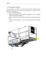
Page 90: ...re distant parts To extend the work platform it is necessary to 1 Push the unlocking pedal A 2 Push the work platform floor manually by grasping it by the railings B beyond the minimum dimensions 3 Ma...

Page 91: ...PAGE 91 Warning while descending from the working position pay warning to possible obstacles beneath the work platform to prevent the platform from overturning or being damaged...

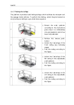
Page 92: ...ccording to the instructions given in sect 4 1 4 Extending the work platform until it has been fully extended 2 Remove the remote push button Unlock the fastenings of the front railing see following p...

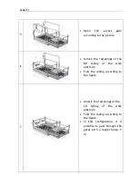
Page 93: ...ings of the RH railing of the work platform Fold the railing according to the figure 7 Unlock the fastenings of the LH railing of the work platform Fold the railing according to the figure In this con...

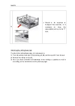
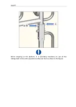
Page 94: ...locking the railing fastenings To unlock the railing fastenings it is necessary to 1 Turn the safety catch A of the locking pin B and then pull it from its seat 2 Remove the safety screw C 3 Once you...

Page 95: ...PAGE 95 Before stepping on the platform it is absolutely mandatory to put all the railings back in the vertical position and secure them as shown in the figure...

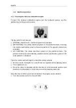
Page 96: ...trols are excluded LH POSITION The whole electrical system of the platform starts The ground controls are automatically enabled and the push button panel in the work platform is disabled Then the cont...

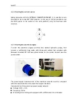
Page 97: ...the electrical engine and thus the related hydraulic pumps first connect a sufficiently long cable with three pole socket that complies with European standard IEC 309 see photo below to the socket lo...

Page 98: ...t disconnect the power to the engine and to the system To start the electrical engine and thus the hydraulic pumps use the ignition key placed on the ground controls this part is the same as described...

Page 99: ...drive in reverse You can work with one track at a time depending on the movement required at that particular moment Travel complies with the maximum safety speed allowed by the technical regulations i...

Page 100: ...towards the right counter rotation Rotation on itself towards the left counter rotation Travel is enabled or disabled depending on the status of the travel approval light located on the control panel...

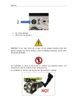
Page 101: ...ion when the ground changes from flat to sloping If this is absolutely necessary perform the manoeuvre gradually It is forbidden to climb on the tracks to attempt any operation that is not allowed or...

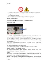
Page 102: ...counter steer and climb up inclined ramps with the platform Hare engine accelerated the left joystick is not active the right joystick 11 controls both tracks The machine can travel only in a straigh...

Page 103: ...ed to a maximum value of 0 4Km h Travel is allowed only up to a height of 4 5 m floor surface In this case too if selector 8 is in hare mode the left joystick is not active and the right joystick 11 c...

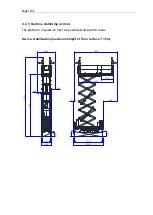
Page 104: ...ne stabilising controls The platform in question has two possible stabilisation areas Narrow stabilisation maximum height of floor surface 7 16m 7160 9160 1000 1130 3230 3480 11 10 2 4 2080 5020 4000...

Page 105: ...ducers allows for the platform to be lifted only if all the stabilisers are on the ground and none of them is completely extended Also all the pins must be completely inserted in their housings If eve...

Page 106: ...tion area or inwards narrow stabilisation area 1 Release the lever once the correct position of the stabiliser has been reached Check that the stabiliser is correctly locked and that the pin is comple...

Page 107: ...e this operation is complete the machine will be levelled and automatically lifted from the ground so that the tracks come off from it The end of the automatic stabilisation phase is signalled by a sh...

Page 108: ...RTANT the machine performs the stabilisation of the frame only by extending the stabilisers but its does not stabilise correctly during the destabilisation phase 4 2 5 3 Manual extension of the stabil...

Page 109: ...with the stabilisers being used IMPORTANT Moving the stabilisers manually is recommended for particular operations during the maintenance and diagnostics phases To stabilise the platform it is advisa...

Page 110: ...of slipping and overturning with the machine on the stabilisers The suggested maximum inclination of the ground under each stabiliser is 10 Carefully check the conditions of the ground before operati...

Page 111: ...PLATFORM Lower than the transport height Higher than the transport height Higher than the transport height Higher than the transport height TRAVEL Allowed at maximum speed Allowed but only at reduced...

Page 112: ...sh button panel The lifting and descent speed are controlled by the electronic control unit ECU The platform descent can also be performed with the combustion engine off but the electrical panel ON Du...

Page 113: ...the following general situations Planarity alarm flashing At least one but not all stabilisers are on the ground OK Work flashing and buzzer At least one pin of the stabilisers is not inserted OK Wor...

Page 114: ...N OK Work OFF Overload alarm OFF Acoustic alarm OFF The work platform cannot be lifted Work platform lifted no more than 4 5 m floor surface machine on tracks lateral and longitudinal inclination of t...

Page 115: ...load alarm OFF Acoustic alarm ON The work platform can descend only Work platform in any position machine on tracks any lateral or longitudinal inclination of the frame Stabiliser pin not inserted Pla...

Page 116: ...ad alarm OFF Acoustic alarm OFF The work platform cannot be lifted Work platform in transport position 4 stabilisers on the ground lateral and longitudinal inclination of the frame lower than or equal...

Page 117: ...stabilisers on the ground lateral and longitudinal inclination of the frame lower than or equal to 0 5 Planarity alarm FLASHING Travel allowed OFF OK Work ON Overload alarm OFF Acoustic alarm OFF Work...

Page 118: ...rms that may occur If there are no alarms present the display will show the hours of work with the electrical engine and with the internal combustion engine d hours of operation with petrol or diesel...

Page 119: ...on the display The control unit can store up to 16 alarms which are shown by pressing the right button of the hour counter These alarms are not cancelled when the machine is turned off The table below...

Page 120: ...than 30 bar 141 No signal from the transducer of the bottom side of stabiliser 1 142 No signal from the transducer of the stem side of stabiliser 1 143 No signal from the transducer of the bottom sid...

Page 121: ...ibility error between the contacts NC and NO of the limit switch of narrow stabilisation of stabiliser 3 157 Compatibility error between the contacts NC and NO of the limit switch of the pin inserted...

Page 122: ...t Disabling and restoring the platform have to occur as follows Shut down the platform according to the indications provided Cover the mobile push button panel with its guard 1 Leave the work platform...

Page 123: ...ol at ground level In this case the operator on the ground remember that at least one operator must be present at ground level to ensure the platform is used in safe conditions must act directly on th...

Page 124: ...d and wait for the platform to have lowered completely Warning This control must be used only in an emergency that is the failure of the hydraulic or electrical system or if it is not possible to brin...

Page 125: ...draulic failure WARNING during these operations it is necessary to keep well away from the scissors paying attention to the limbs In this condition the descent speeds of the platform are different fro...

Page 126: ...s not working but it is possible to turn on the internal combustion engine or the electrical engine then it will be possible to perform then movements of the machine directly from the hydraulic block...

Page 127: ...ve the left track completely turn the screw of solenoid valve EV1 A clockwise 6 Keep pressed using a special tool solenoid valve EV4A Forwards or EV4B backwards IMPORTANT The two proportional valves A...

Page 128: ...first 20 hours X Replace engine oil filter X X Clean the engine air filter X X Replace engine air filter X Track inspection and tensioning X X Check the condition of the tracks X X Check the runners f...

Page 129: ...rces Attention It is mandatory to perform all MEWP movements required for inspections maintenance using the ground controls and without operators on the work platform When checking machine operation f...

Page 130: ...With the platform in the transport configuration place the machine without lowering the stabilisers with the frame tilted with respect to the horizontal by a value greater than 2 on the lateral Operat...

Page 131: ...lination of the frame with respect to the horizontal exceeds 2 To resume the control of the machine it is necessary to lower the work platform in the transport position Lift the platform to a height g...

Page 132: ...e sure it works Check the operation of the buzzer when the travel or work platform descent functions are used With the machine travelling and the platform in the transport position make sure that when...

Page 133: ...e Ma torque Resistance class in accordance with DIN ISO 898 8 8 Yielding point Rp 0 2 N mm 640 for M16 660 for M16 Metric thread ISO Cross section of the powered zone Cross section of the thread Clamp...

Page 134: ...rs Condition of the frame and stabilisers Condition of the tracked chassis In particular check if there is any rust in the structure Status of the rubber tracks Oil leaks Pins and their stop devices 6...

Page 135: ...rsh conditions e g damp or dusty places marine environments etc The surfaces to be greased are those in contact with the runners both in the frame and under the work platform see figures below Remove...

Page 136: ...nd topping up if necessary The hydraulic oil level is checked by means of a level indicator located directly on the tank The correct oil level must be checked with the machine in the configuration ind...

Page 137: ...PAGE 137 In this configuration the oil level B must be at a distance of 30mm from the maximum level C...

Page 138: ...PAGE 138...

Page 139: ...general chart 1 Collect the used oil in a suitable vessel and dispose of it in the proper way 2 Empty the tank using the manual 2 or electric 3 pump making use of the filler cap placed on top of the t...

Page 140: ...o the outlets 4 and 5 a Start the internal combustion engine b Perform the movements of the stabilisers until the limit switch has been reached and keep them in this position for a few seconds This ac...

Page 141: ...er adjustment unless the hydraulic circuit is replaced the actual pressure relief valve is replaced In these cases the valve must be calibrated by SPECIALIZED PERSONNEL according to the monitoring pro...

Page 142: ...Do not place tools or any other metal object on the battery Clean any encrustations from the battery terminals and always tighten them correctly Always keep the battery clean dry and free from oxidati...

Page 143: ...le of the battery charger to the 150A fuse or to the dedicated connector placed under the engine connect the negative pole of the battery charger to the frame Disconnect the battery charger when the r...

Page 144: ...rms to the following specifications Voltage 230 v 10 Frequency 50 Hz Grounding line working and equipped with a differential circuit breaker Use an extension power cord with an appropriate section dep...

Page 145: ...Hydraulic filter replacement Replace the discharge filters of the hydraulic circuit at the frequencies indicated in the general chart The hydraulic oil tank features 2 or 4 suction filters inside the...

Page 146: ...place 6 Work through the instructions above in reverse order to restore the machine to its normal operating conditions 7 Seal the lid with sealing paste 8 Fill the hydraulic oil reservoir with oil and...

Page 147: ...ions some oil could spill Remove spilt oil with a cloth or place a vessel underneath so that the oil drains into it ONLY USE GENUINE SPARE PARTS when replacing the filters Contact the ALMAC technical...

Page 148: ...environments etc The surfaces to be greased are those in contact with the runners both in the frame and under the work platform see figures below Remove all dirt from the parts before greasing Use gre...

Page 149: ...ncy indicated in the general chart and as specified for the runners The surfaces to be greased are those in contact with the wheels both in the fixed part of the platform and in the extension see figu...

Page 150: ...utomatic levelling control on stabilisers make sure that the system automatically brings the frame to the horizontal position With the platform in the transport configuration and stabilised on the tra...

Page 151: ...that the vertical distance between the ends of the scissors must be greater than 50mm Further movements downwards are possible only after a 3s delay at reduced speed Check the operation of the travel...

Page 152: ...Voltage 230 v 10 Frequency 50 Hz Grounding line working and equipped with a differential circuit breaker Use an extension power cord with an appropriate section depending on its length Press the butto...

Page 153: ...to the outlet on the work platform At this point it is necessary to simulate a dispersion by making a bridge with a cable between the outlet on the work platform and a grounding point of the machine T...

Page 154: ...e is a manual pump which allows to move the platform up and or down in any condition that is With the combustion engine off When the electrical system is faulty or off In the absence of battery voltag...

Page 155: ...abiliser cylinders To perform this check it is necessary to 1 Place the machine as shown in the figure platform completely lowered and stabilised on the stabilisers with the cylinders extended not to...

Page 156: ...ylinders To perform this check it is necessary to carry out a procedure from the control push button panel 1 Stabilise the machine on the stabilisers 2 Press the emergency button on the control push b...

Page 157: ...id valve EV19 of the upper cylinder will be energised 12 After this a countdown will begin during which solenoid valve EV21 of the lower cylinder will be energised If when valve EV19 is energised valv...

Page 158: ...V21 SV19 PS3 LOWER CYLINDER UPPER CYLINDER PS2 PS1 31 31 31 31 18 21 19 32 32 Solo nella 1470 Warning if the test has a negative outcome do not use the machine and contact a qualified technician train...

Page 159: ...PAGE 159 6 2 18 Maintenance of the engine Below are general instructions for the correct maintenance of the engine In any case always consult the use and maintenance manual of the engine...

Page 160: ...PAGE 160...

Page 161: ...PAGE 161...

Page 162: ...PAGE 162...

Page 163: ...PAGE 163...

Page 164: ...PAGE 164...

Page 165: ...PAGE 165...

Page 166: ...PAGE 166...

Page 167: ...PAGE 167...

Page 168: ...PAGE 168...

Page 169: ...rds slightly the deformation should be about 2 cm If the track sags and becomes too noisy as it moves it must be tightened as described below 1 Remove the guards 1 2 For proper track tension use a ten...

Page 170: ...ng them when the tread is equal to or less than 10 mm The tracks must be changed even before they reach this limit if they are cuts or tears are noted Tracks must only be replaced by specialized prope...

Page 171: ...ople WARNING USE PERSONAL PROTECTIVE DEVICES Replacing the track The track must be replaced when 10 mm of tread is left or even earlier if there are any cuts Proceed as follows 1 Do not lift the machi...

Page 172: ...PAGE 172 6 Using the nut supplied point A 7 Move the front wheel back by pressing on the track with your foot...

Page 173: ...el 10 To install the new track proceed as indicated in the previous points but in reverse order 11 The track is correctly tensioned by using the tensioning kit pumping grease until the pressure indica...

Page 174: ...he oil level frequency indicated in the scheduled maintenance and checks table 1 Move until the gear motor is in the condition in which the FILL cap is at the top and perpendicular to the DRAIN cap 2...

Page 175: ...ake it must be recovered for recycling purposes where possible Note ALMAC S r l declines all liability for damage to persons animals or things deriving from reuse of parts of the equipment for functio...

Page 176: ...s of it because the combustion products of plastic materials and paints could develop harmful polluting gases 7 3 Battery disposal Battery recycling is mandatory European Directive 2006 66 EC and reco...

Page 177: ...ective 2006 42 EC The purpose of this Register is to record events concerning the life of the machine in detail Mandatory routine inspections INAIL ASL authorized bodies Maintenance and obligatory ins...

Page 178: ...PAGE 178 MANDATORY ROUTINE INSPECTIONS Date Observations Seal Signature...

Page 179: ...y of the operation as indicated in the table in Chapter 6 Daily registration is not necessary but should be made at least once a year when other operations are performed Type of inspection Description...

Page 180: ...Signature 1st year 2nd year 3rd year 4th year 5th year 6th year 7th year 8th year 9th year 10th year NOTE frequency of the operation as indicated in the table in Chapter 6 Monthly registration is not...

Page 181: ...ations Signature 1st year 2nd year 3rd year 4th year 5th year 6th year 7th year 8th year 9th year 10th year NOTE frequency of the operation as indicated in the table in Chapter 6 Daily registration is...

Page 182: ...d year 3rd year 4th year 5th year 6th year 7th year 8th year 9th year 10th year NOTE frequency of the operation as indicated in the table in Chapter 6 Type of inspection Description Hydraulic filter r...

Page 183: ...r 5th year 6th year 7th year 8th year 9th year 10th year NOTE frequency of the operation as indicated in the table in Chapter 6 Type of inspection Description Check the operation of the differential s...

Page 184: ...f present Date Observations Signature 1st year 2nd year 3rd year 4th year 5th year 6th year 7th year 8th year 9th year 10th year NOTE frequency of the operation as indicated in the table in Chapter 6...

Page 185: ...year 6th year 7th year 8th year 9th year 10th year NOTE frequency of the operation as indicated in the table in Chapter 6 Daily registration is not necessary but should be made at least once a year wh...

Page 186: ...r 6th year 7th year 8th year 9th year 10th year NOTE frequency of the operation as indicated in the table in Chapter 6 Daily registration is not necessary but should be made at least once a year when...

Page 187: ...8th year 9th year 10th year NOTE frequency of the operation as indicated in the table in Chapter 6 Daily registration is not necessary but should be made at least once a year when other operations ar...

Page 188: ...valves of the lifting cylinders Check the seal Date Observations Signature 1st year 2nd year 3rd year 4th year 5th year 6th year 7th year 8th year 9th year 10th year NOTE frequency of the operation as...

Page 189: ...apter 6 Serious faults Date Description of fault Solution Spare parts used Description Code qty Serious faults Date Description of fault Solution Spare parts used Description Code qty Serious faults D...

Page 190: ...eristics and that variations if any have been recorded in the register Seller s business name Seller Purchaser Copy to send to ALMAC SRL on ownership of the MEWP serial no year of manufacture was tran...

Page 191: ...PAGE 191 8 4 Hydraulic diagram See attachment 8 5 Wiring diagram See attachment...

Page 192: ...S _________________________________________________ 19 1 11 1 Intended use __________________________________________________________ 19 1 11 2 Improper uses___________________________________________...

Page 193: ...NT ________________________________________________________ 67 3 4 PLATFORM OPERATION SAFETY DEVICES______________________________________________ 68 3 4 1 Main frame inclination control device ______...

Page 194: ..._________________ 104 4 2 5 1 Automatic stabilisation _____________________________________________________ 107 4 2 5 2 Voluntary extension of the stabilisers ________________________________________...

Page 195: ...2 6 2 8 3 1 Charging method No 1 with 12V battery charger____________________________ 143 6 2 8 3 2 Charging method No 2 using the 230V plug in the ladder_____________________ 143 6 2 8 3 3 Charging m...

Page 196: ...__________________________________________________________ 176 8 ATTACHMENTS ______________________________________________________________ 177 8 1 DECLARATION OF CONFORMITY __________________________...

Reviews: