PAGE
106
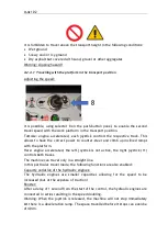
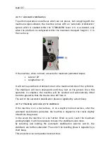
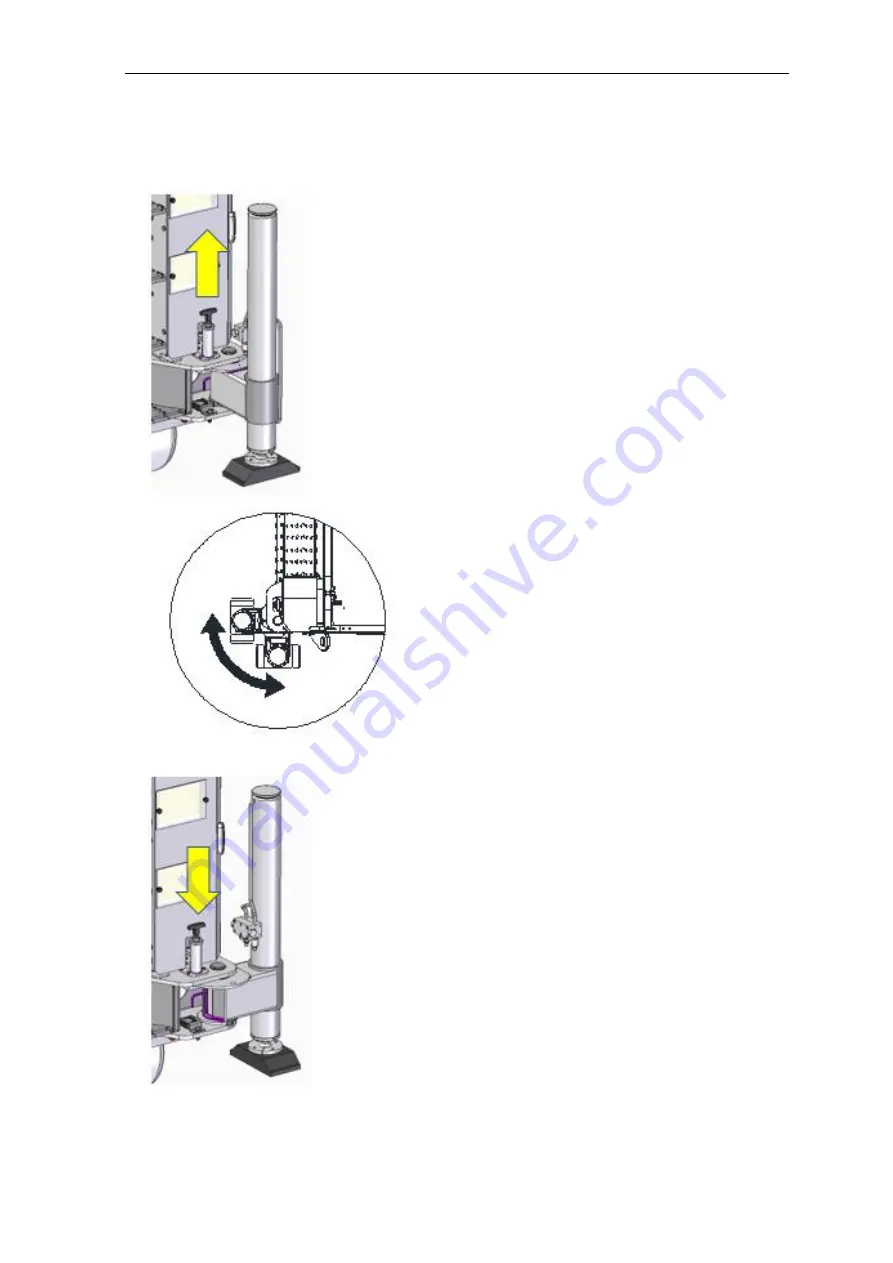
The operations required to select the stabilisation area are the following:
3.
Pull the locking lever upwards.
2.
Turn the stabiliser outwards (wide
stabilisation area) or inwards (narrow
stabilisation area)
1.
Release the lever once the correct
position of the stabiliser has been
reached.
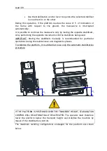
Check that the stabiliser is correctly
locked and that the pin is completely
inserted. If it is not completely
inserted, an acoustic alarm and the
flashing ok work indicator light will
warn the operator that the position is
not correct.
Summary of Contents for 1470-HE EVO
Page 7: ...PAGE 7...
Page 12: ...PAGE 12 Work area on tracks Travel not allowed Maximum inclination allowed 2 5020 5490 7500...
Page 27: ...PAGE 27...
Page 28: ...PAGE 28...
Page 34: ...PAGE 34 Warning Do not tighten the fixing belts too much so as not to damage the eye bolts...
Page 50: ...PAGE 50 8 Extendible basket pedal...
Page 57: ...PAGE 57 38 Chassis and stabilisers...
Page 74: ...PAGE 74...
Page 76: ...PAGE 76...
Page 77: ...PAGE 77...
Page 80: ...PAGE 80...
Page 138: ...PAGE 138...
Page 160: ...PAGE 160...
Page 161: ...PAGE 161...
Page 162: ...PAGE 162...
Page 163: ...PAGE 163...
Page 164: ...PAGE 164...
Page 165: ...PAGE 165...
Page 166: ...PAGE 166...
Page 167: ...PAGE 167...
Page 168: ...PAGE 168...
Page 178: ...PAGE 178 MANDATORY ROUTINE INSPECTIONS Date Observations Seal Signature...
Page 191: ...PAGE 191 8 4 Hydraulic diagram See attachment 8 5 Wiring diagram See attachment...

