PAGE
140
6.2.7
Checking the operation of the maximum pressure valves
With the frequency indicated in the general chart, check the operation of the
maximum pressure valves of the distributor.
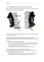
To test them, connect two pressure gauges with a full scale of 250 bar to the
pressure outlets (4 and 5).
Checking the general maximum pressure valves of the system (1 and 2)
The pressure gauges relating to these valves are those connected to the outlets
4 and 5.
a)
Start the internal combustion engine.
b)
Perform the movements of the stabilisers until the limit switch has been
reached and keep them in this position for a few seconds. This activates
the maximum pressure valve of the circuit.
c)
Read the pressure on the gauge, which should be 200 bar ± 5 bar
Checking the maximum pressure valves relating to lifting (3)
The pressure gauge relating to this valve is the one connected to outlet 4.
d)
Start the internal combustion engine.
e)
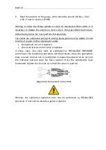
Press the platform "up" button (
13
) until it reaches the limit and hold it
down. This activates the pressure relief valve of the lift circuit.
Summary of Contents for 1470-HE EVO
Page 7: ...PAGE 7...
Page 12: ...PAGE 12 Work area on tracks Travel not allowed Maximum inclination allowed 2 5020 5490 7500...
Page 27: ...PAGE 27...
Page 28: ...PAGE 28...
Page 34: ...PAGE 34 Warning Do not tighten the fixing belts too much so as not to damage the eye bolts...
Page 50: ...PAGE 50 8 Extendible basket pedal...
Page 57: ...PAGE 57 38 Chassis and stabilisers...
Page 74: ...PAGE 74...
Page 76: ...PAGE 76...
Page 77: ...PAGE 77...
Page 80: ...PAGE 80...
Page 138: ...PAGE 138...
Page 160: ...PAGE 160...
Page 161: ...PAGE 161...
Page 162: ...PAGE 162...
Page 163: ...PAGE 163...
Page 164: ...PAGE 164...
Page 165: ...PAGE 165...
Page 166: ...PAGE 166...
Page 167: ...PAGE 167...
Page 168: ...PAGE 168...
Page 178: ...PAGE 178 MANDATORY ROUTINE INSPECTIONS Date Observations Seal Signature...
Page 191: ...PAGE 191 8 4 Hydraulic diagram See attachment 8 5 Wiring diagram See attachment...

