PAGE
150
6.2.12
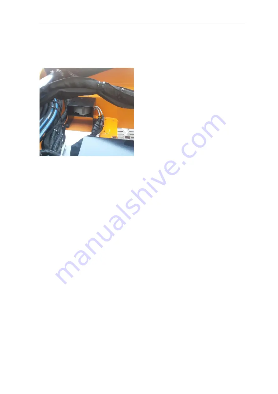
Checking the operation of the frame angle sensor
With the frequency indicated in the general chart, check the frame angle
sensor.
•
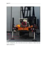
With the platform in the transport configuration, place the machine with
the frame tilted with respect to the horizontal by a value greater than
0.5° on the lateral. Operate the automatic levelling control on stabilisers,
make sure that the system automatically brings the frame to the
horizontal position
•
With the platform in the transport configuration, place the machine with
the frame tilted with respect to the horizontal by a value greater than
0.5° on the longitudinal. Operate the automatic levelling control on
stabilisers, make sure that the system automatically brings the frame to
the horizontal position
•
With the platform in the transport configuration and stabilised on the
tracks, place the machine with the frame tilted with respect to the
horizontal by a value greater than 2° on the longitudinal. Operate the
platform lifting control and make sure that it is not possible to raise the
platform.
•
With the platform in the transport configuration and stabilised on the
tracks, place the machine with the frame tilted with respect to the
horizontal by a value greater than 2° on the lateral. Operate the platform
lifting control and make sure that it is not possible to raise the platform.
If the operations described above take place in the indicated sequence, it
means that the angle sensor is working properly.
Summary of Contents for 1470-HE EVO
Page 7: ...PAGE 7...
Page 12: ...PAGE 12 Work area on tracks Travel not allowed Maximum inclination allowed 2 5020 5490 7500...
Page 27: ...PAGE 27...
Page 28: ...PAGE 28...
Page 34: ...PAGE 34 Warning Do not tighten the fixing belts too much so as not to damage the eye bolts...
Page 50: ...PAGE 50 8 Extendible basket pedal...
Page 57: ...PAGE 57 38 Chassis and stabilisers...
Page 74: ...PAGE 74...
Page 76: ...PAGE 76...
Page 77: ...PAGE 77...
Page 80: ...PAGE 80...
Page 138: ...PAGE 138...
Page 160: ...PAGE 160...
Page 161: ...PAGE 161...
Page 162: ...PAGE 162...
Page 163: ...PAGE 163...
Page 164: ...PAGE 164...
Page 165: ...PAGE 165...
Page 166: ...PAGE 166...
Page 167: ...PAGE 167...
Page 168: ...PAGE 168...
Page 178: ...PAGE 178 MANDATORY ROUTINE INSPECTIONS Date Observations Seal Signature...
Page 191: ...PAGE 191 8 4 Hydraulic diagram See attachment 8 5 Wiring diagram See attachment...

