PAGE
45
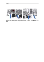
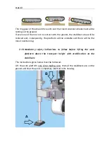
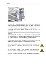
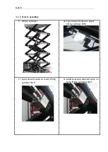
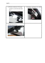
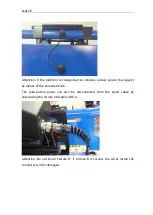
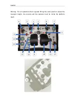
The photo above shows how the locking system of the extensible structure
must be positioned during maintenance work. By means of the "ground
controls", it is possible to lift the work platform until it is possible to place
the two locking brackets vertically and aligned with the pins below.
Subsequently lower the work platform until the brackets are locked in the
relative pins.
Warning: during this procedure, there must be no load or people on the work
platform.
Warning: during this procedure, if it is not necessary to remove one or both
the lifting cylinders, it is advisable to allow the structure to be supported by
the cylinders themselves. Position the brackets as additional safety.
•
Protect the environment: avoid spilling oil when changing it or topping up.
Used oil must be disposed of in accordance with the laws in force.
•
Never insert the body, limbs or fingers in sharp, jointed opening on the
machine that is not controlled or without proper guards unless securely
blocked.
•
Do not use petrol, solvents or other flammable liquids as detergents.
Always use authorized non-flammable and non-toxic commercial products.
•
Do not use open flames for lighting purposes when performing maintenance.
Summary of Contents for 1470-HE EVO
Page 7: ...PAGE 7...
Page 12: ...PAGE 12 Work area on tracks Travel not allowed Maximum inclination allowed 2 5020 5490 7500...
Page 27: ...PAGE 27...
Page 28: ...PAGE 28...
Page 34: ...PAGE 34 Warning Do not tighten the fixing belts too much so as not to damage the eye bolts...
Page 50: ...PAGE 50 8 Extendible basket pedal...
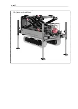
Page 57: ...PAGE 57 38 Chassis and stabilisers...
Page 74: ...PAGE 74...
Page 76: ...PAGE 76...
Page 77: ...PAGE 77...
Page 80: ...PAGE 80...
Page 138: ...PAGE 138...
Page 160: ...PAGE 160...
Page 161: ...PAGE 161...
Page 162: ...PAGE 162...
Page 163: ...PAGE 163...
Page 164: ...PAGE 164...
Page 165: ...PAGE 165...
Page 166: ...PAGE 166...
Page 167: ...PAGE 167...
Page 168: ...PAGE 168...
Page 178: ...PAGE 178 MANDATORY ROUTINE INSPECTIONS Date Observations Seal Signature...
Page 191: ...PAGE 191 8 4 Hydraulic diagram See attachment 8 5 Wiring diagram See attachment...

