background image

PAGE

137 


ALMAC s.r.l.


6.2.16


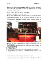
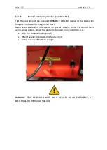
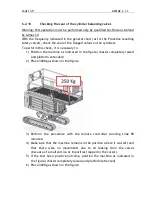
Manual emergency device operation test 

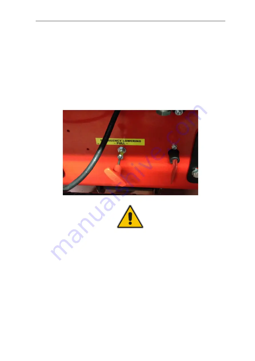
Test the operation of the manual EMERGENCY DESCENT device at the inspection 
frequency indicated in the general chart. 
Near the access ladder, indicated with special stickers, there is a control lever 
which, when pulled, allows the platform to lower in any condition, i.e.: 


With the combustion engine off 


When the electrical system is faulty or off 


In the absence of battery voltage 


WARNING:

  THIS  MECHANISM  MUST  ONLY  BE  USED  IN  AN  EMERGENCY,  i.e. 

ELECTRICAL OR HYDRAULIC FAILURE. 


Summary of Contents for 850-BL EVO

Page 1: ...ENA 850 BL EVO Translationoforiginalinstructions Prior to commissioning the machine read carefully this Use and Maintenance Manual Note table of contents at the end of the manual Edition Date 00 23 02 2018 ...

Page 2: ...m Version ATHENA 850 BL EVO Note Some of the photos and illustrations may not refer specifically to the version of the machine in your possession but provide indications concerning the purpose for which they have been included RECIPIENTS OF THIS MANUAL User Maintenance technician Warning the servicing personnel must be properly trained and experienced CAREFULLY READ this manual before performing a...

Page 3: ...ent with the technical and safety specifications of the machine to which the manual refers The manufacturer declines all liability for direct or indirect damage to persons things or animals deriving from use of the machine in conditions differing from those envisaged ALMAC s r l reserves the right to make changes or improvements without prior notice to the documentary material and to the machines ...

Page 4: ...ASPAC GROUP ELEVATING WORK PLATFORM MANUFACTURER ALMAC s r l CAUTION THIS PLATFORM IS NOT VOLTAGE INSULATED YEAR OF MANUFACTURE DATE OF TEST RATED LOAD INC 2 OCCUPANT TOOLS MAX ALLOWABLE SIDE FORCE MAX WIND SPEED MAX PLATFORM HEIGHT MAX WORKING HEIGHT MAX HORIZONTAL WORKING OUTREACH MAX UPPER GRADIENT IN RUNNING DIRECTION COUNTRY OF MANUFACTURE HYDRAULIC PRESSURE TRAVEL HYDRAULIC PRESSURE ELEVATIN...

Page 5: ...PAGE 5 ALMAC s r l Refer to the data on the identification plate for an exact identification of the MEWP ...

Page 6: ...have during operation and transport F2 F1 A4 D3 D1 1940 1630 A3 E D4 D2 C2 C3 C1 B A1 A2 D6 D5 Dismantle only for special transport situations before commissioning the machine must be reconfigured by skilled and authorised personnel according to the certified diagram following the manufacturer s instructions ...

Page 7: ...PAGE 7 ALMAC s r l MAXIMUM WORKING HEIGHT TRAVELLING NOT PERMITTED H1 H2 G3 H3 H4 G4 G1 L1 G2 ...

Page 8: ...D2 mt 2 50 Min height of floor surface Narrow track D3 mt 1 64 Minimum height Narrow track D4 mt 2 80 Minimum height transport only Widened track railings closed D5 mt 1 99 Minimum height transport only Narrow track railings closed D6 mt 2 29 Width of work platform E mt 0 79 Distance between the crawler and the edge of the work platform in width Narrow track F1 mm 260 Distance between the crawler ...

Page 9: ...h 2 0 Maximum speed with platform lifted km h 0 4 Overall weight kg 2060 Max wind force m s 12 5 Starter battery voltage and capacity V Ah 12 50 Weight of starter battery kg 15 Sound power LwA dBA 104 Sound level at operator position Lp indoor industrial environment dBA 84 5 2 6 Sound level at operator position Lp outdoor environment on asphalt dBA 79 5 2 6 Max peak level Lp peak dBC 106 0 Vibrati...

Page 10: ...PAGE 10 ALMAC s r l ...

Page 11: ...LMAC s r l Maximum transport height allowed manual levelling and the adjustment of the travel speed is allowed Maximum travel height allowed manual levelling and the adjustment of the travel speed is not allowed ...

Page 12: ...rage points Doubled capacity on the lifting cylinder Electric starter on work platform Overload control Dynamic levelling system of the machine Electronic anti shearing protection Electronic tilt control Proactive levelling system Engine specifications Z602 E3B TIER 4 Dry weight 53 1 kg Type of engine VERTICAL 4 CYCLE LIQUID COOLED Swept volume 479 cm3 Net power 9 9 kW 3600 rpm Net torque 30 Nm 25...

Page 13: ...es the anti shearing function has been used as provided for in section 5 4 3 of UNI EN 280 2015 with permanent warning signs 1 8 Warranty ALMAC S r l guarantees the equipment it manufactures and undertakes to replace free of charge and within the shortest possible time those parts that in its opinion possess manufacturing and or material defects Work under guarantee must only be performed by works...

Page 14: ...This information is given on the identification plate of the equipment 1 9 Assistance As far as the optimum use of the machine and extraordinary maintenance are concerned this manual does not replace the expertise of the Technical Assistance sent by ALMAC S r l refer also to the Maintenance Chapter 1 9 1 Request for assistance and repairs To request ALMAC S r l specialized Assistance Service the C...

Page 15: ...ecify the serial number of the machine given on the relative identification plate when requesting a new copy of the manual The manufacturer undertakes to provide a new copy Note When selling used equipment this manual and the related attachments must be included and the manufacturer must be informed of the new owner see Appendix 3 Transfer of Ownership Read carefully Chapter 1 General Information ...

Page 16: ... technical specifications The platform was designed and built to be driven only from the console located on the work platform The push button is of the removable type and can only be used by the operator to control the platform exclusively in transport position The controls on the ground on the rear side are for EMERGENCY use or MAINTENANCE by qualified personnel Warning NEVER exceed the machine s...

Page 17: ...ATION IN ATEX CLASSIFIED ATMOSPHERES ALL LOADS must be positioned inside the work platform NEVER LIFT LOADS HANGING FROM THE PLATFORM from the lifting structure or from the railings If the machine is used in places open to the public or in construction sites where persons may transit or remain in the vicinity the WORK AREA MUST BE CORDONED OFF in a suitable way e g chains and posts ...

Page 18: ... are for EMERGENCY use or MAINTENANCE by qualified personnel The push button panel is of the removable type and can only be used by the operator to control the platform exclusively in transport position 1 11 3 Cases that relieve the manufacturer from liability The manufacturer declines all liability in the following cases Use not indicated in this manual Improper use of the machine or its use by u...

Page 19: ...nce Against Industrial Accidents INAIL for the purpose of registering the platform Once the platform has been registered ROUTINE INSPECTIONS must begin The FIRST of these is performed by INAIL within 45 days since 21 August 2013 from the date on which the platform is put into service The successive inspections to be carried out at the frequency indicated in Annex VII to Legislative Decree D Lgs 81...

Page 20: ... of changes induced by use of alcohol or drugs psychological equilibrium absence of depression or stress Operators who use the machine for professional purposes must undergo health surveillance as required by Legislative decree D Lgs 81 2008 and successive amendments particularly with regard to alcohol addiction and alcohol concentration tests The law that currently governs health control and surv...

Page 21: ...RAINS OR CRACKS THAT OPEN UP TO EMPTY SPACES EN THE OPERATOR IS PROHIBITED TO MOVE BETWEEN THE BASKET AND A STRUCTURE OUTSIDE THE MACHINE MACHINE STABILITY COULD BE JEOPARDISED PERSONNEL AND THE EQUIPMENT MUST ENTER AND EXIT THE CAGE ONLY WITH THE SCISSOR IN STOWED POSITION AND BASKET RETRACTED THE OPERATOR IS PROHIBITED TO MOVE BETWEEN THE BASKET AND A STRUCTURE OUTSIDE THE MACHINE MACHINE STABIL...

Page 22: ...n Maximum inclination of the ground Front inclination of the ground The maximum front inclination of the ground to stay safe is 25 There is no electronic control for this condition which is at the discretion of the operator Lateral inclination of the ground The maximum lateral inclination of the ground keeping the frame as level as possible to stay safe is 25 There is no electronic control for thi...

Page 23: ...PAGE 23 ALMAC s r l ...

Page 24: ...es substitute this Manual which is the only reference document containing complete information Comply with the indications on the sign plates Failure to comply with these indications may result in serious injuries and even death and in any case could endanger the operators and or exposed persons Make sure that the sign plates are always affixed and legible If this is not the case they must be fast...

Page 25: ... injury to the upper and lower limbs due to moving parts Do not insert your hands or feet into openings that could move and cut or between moving parts Forbidden Means that it is forbidden to use water at high pressure on these surfaces Forbidden Means that it is forbidden to climb onto the parts indicated by this symbol Sign plate Take care of the moving scissor components Compulsory This sign pl...

Page 26: ...ur footwear before getting on the M E W P THE OPERATOR MUST NOT MOVE BETWEEN THE WORK PLATFORM AND A STRUCTURE OUTSIDE THE MACHINE THE MACHINE MAY BECOME UNSTABLE THE PERSONNEL AND THE EQUIPMENT MUST ENTER AND EXIT THE WORK PLATFORM ONLY WITH THE PLATFORM IN THE TRANSPORT POSITION Do not use the controls or flexible hoses as hand grips Do not lean over the railings around the work platform Warn th...

Page 27: ...ine can be loaded onto the vehicle in two different ways 1 Using chutes and the platform driving controls after having fully LOWERED the platform the operator can operate the machine by following the instructions given in the dedicated chapter driving directly onto the transport means In this case make sure that the ramp gradient is within the gradeability indicated in the PERFORMANCE data and tha...

Page 28: ...ransport position the operator can move the machine directly from the ground using the portable push button panel 2 Lifting the platform using a CE certified beam not included and using hooks and steel steel ropes hooked to the holes marked with signs see photo below 370 16 Warning the maximum weight of ATHENA BL in the heaviest configuration is 2150Kg ...

Page 29: ... must be folded Note Once the machine has been loaded onto the vehicle it must be fastened in place using belts connect them to the special red eye bolts Note Make sure that the platform is FULLY LOWERED before transporting the machine Warning the chassis must be completely lowered chassis wide Warning Do not tighten the fixing belts too much so as not to damage the eye bolts ...

Page 30: ...and correctly in place with their washers Make sure that all the pins are in place and correctly secured Check that the steel structure is not deformed Make sure there are no cracks in the welds damage or abnormal wear Make sure the tracks are not cut or abnormally worn Always check to make sure that the track tension is correct Check and if necessary grease the scissor runners both those in conta...

Page 31: ...hine if the wind speed exceeds 12 5 m s Use the MEWP only within the allowed temperature range It is forbidden to get on or off the MEWP when the platform is raised It is forbidden to load or unload objects from the MEWP when the platform is raised It is forbidden to exceed the capacity of the MEWP the capacity is the work load for which the platform has been designed and includes the weight of th...

Page 32: ...CTION on kerbs rocks or appreciable differences in level 10 cm when driving the machine In this case always proceed perpendicularly to the obstacles If you must drive up a slope do not change direction when the ground changes from flat to sloping If this is absolutely necessary perform the manoeuvre gradually Do not drive along the edge of slopes or over uneven ground with one track horizontal and...

Page 33: ... platform is lowered Warning for inclined floors pay warning to the correct LEVELLING direction Avoid inclining the platform beyond what is necessary towards the lower side of the platform Warning manual levelling is allowed only when the transit area of the platform is lower than 2mt from the ground Avoid smooth slippery and or icy surfaces and those covered with sand they could cause a risk of s...

Page 34: ...PAGE 34 ALMAC s r l NO ICE NO SAND NO DUST OR SMOOTH SURFACES Warning during movement with ELECTRICAL POWER be careful of the connection cable in order to avoid dangerously crushing the cable itself ...

Page 35: ... the platform in the transport configuration place the machine with the frame tilted with respect to the horizontal by a value greater than 0 5 on the lateral Operate the platform lifting control make sure that the system automatically brings the frame to the horizontal position With the platform in the transport configuration place the machine with the frame tilted with respect to the horizontal ...

Page 36: ...he machine only at reduced speed light indicator 2 flashing Also make sure that at greater heights the light indicator 2 turns off and that it is not allowed to move Check that with the platform lifted higher than the transport height but lower than the maximum travel height light 2 on and moving on non level terrain the machine stops automatically when the inclination of the frame with respect to...

Page 37: ... leave the MEWP unattended without having first stopped the engine and removed the keys from the control panel to prevent the machine from being used by unauthorized persons 2 12 Safety regulations during maintenance The maintenance operations described in this Manual refer to platforms in conditions of normal use In heavy duty use conditions e g extreme temperatures dust and corrosive substances ...

Page 38: ...s make sure the platform is completely blocked If the work platform must be raised for maintenance purposes the platform and lifting structure must be prevented from accidentally lowering To do this there is a device on the lift arm that must be set in a precise position so as to immobilize the scissor structure see procedure described below The MEWP is equipped with two devices on the sides of th...

Page 39: ...rely blocked Do not use petrol solvents or other flammable liquids as detergents Always use authorized non flammable and non toxic commercial products Do not use open flames for lighting purposes when performing maintenance Make sure there are no fluids under pressure before disassembling unions or pipes oil spattering out under pressure can cause serious injuries Immediately call a physician if i...

Page 40: ...to completely prevent falling from a height The safety device consists of a full body harness 1 complying with UNI EN 361 with front or rear coupling equipped with retaining or adjustable lanyard 2 for EN 358 which allows to prevent the fall hooked to the pre arranged hooking point in the basket by means of connectors 3 EN 362 having a suitable shape and dimensions Once climbed onto the work platf...

Page 41: ... This device is not to be considered a fall protection system it is only used to prevent the fall PERSONAL PROTECTION EQUIPMENT Body protection required Protective gloves required Safety shoes required Hearing protection required ...

Page 42: ...3 DESCRIPTION OF THE MACHINE 3 1 Structure of the equipment This section describes the main components of the machine and their functions 3 1 1 Work platform assembly 3 1 2 Scissor assembly 3 1 2 Tank and chassis assembly ...

Page 43: ...ssembly 1 Control push button panel console 2 Control console emergency button 3 Glove box 4 Extensible work platform 5 Spirit level 6 Socket on work platform 7 Device for the extension of the work platform 8 Device to access the work platform ...

Page 44: ...PAGE 44 ALMAC s r l 3 1 2 Scissor assembly 9 Lifting cylinder 10 Lifting cylinder shut off valve 11 Pressure transducer for load control 12 Scissor angle sensor 9 10 11 ...

Page 45: ...GE 45 ALMAC s r l 3 1 3 Tank assembly 13 Ladder to access the platform 14 Main hydraulic unit 15 Main differential panel 16 Ground control panel 17 Flashing light 18 Ground control panel emergency button ...

Page 46: ...PAGE 46 ALMAC s r l 19 ECU electronic control unit 20 Battery disconnect switch 21 Emergency descent device 22 Hydraulic oil tank 23 Discharge filter 24 Intake filters in the tank 24 23 ...

Page 47: ...PAGE 47 ALMAC s r l 25 Oil tank refill cap 26 Visual hydraulic oil level 27 Combustion engine starter battery 28 Booster for management of third travel speed 26 ...

Page 48: ...C s r l 29 Electrical engine 30 Inverter differential panel if present 31 Frame angle sensor 32 Proactive levelling angle sensor 33 Proactive levelling safety valves 34 Proactive levelling limit switch 33 34 35 36 ...

Page 49: ...PAGE 49 ALMAC s r l 35 Combustion engine 36 Fuel tank 37 Bi levelling chassis 37 38 ...

Page 50: ...pped with a mobile control push button panel console which allows for normal operation on the work platform The console can be located in the dedicated metal support attached to the railing of the platform or removed and held by the operator Even the metal support can be removed by unscrewing the special knob ...

Page 51: ...h button panel can also be disconnected from the spiral cable by unscrewing the ferrule indicated with A Warning Do not touch ferrule B if ferrule B is turned the wires inside the connector will be damaged The push button panel can be placed in a compartment closed with a locked hatch and located on the left side of the access ladder ...

Page 52: ...PAGE 52 ALMAC s r l Warning For all operations that required lifting the work platform above the transport height the console and the operator must be inside the platform itself ...

Page 53: ...does not exceed the maximum allowed transit height Lateral inclination 3 Longitudinal inclination 3 ON If the platform exceeds the maximum allowed transit height Lateral inclination 0 5 Longitudinal inclination 0 5 2 Indicator light TRAVEL ENABLING with indicator light 3 on OFF Travel not allowed proactive levelling allowed if 4 5mt FLASHING Travel and proactive levelling allowed but at the height...

Page 54: ...sition Standard operation with internal combustion engine On the work platform the 230V outlet is not powered unless the plug under the ladder has been connected to an external power source ELECTRICAL ENGINE position Turning the internal combustion engine off and enabling the electrical engine To turn on the electrical engine it is necessary to turn selector 5 ON The electrical engine works only i...

Page 55: ...HARE position High speed for all movements Dynamic levelling ON 10 LH joystick Left track FORWARD REVERSE travel control 11 RH joystick Right track FORWARD REVERSE travel control 12 Selector switch Left levelling 13 Selector switch Right levelling 14 Selector switch Longitudinal levelling 15 Selector switch Ascent descent 16 Indicator light REMOTE CONTROL BATTERY STATUS INDICATOR if present 17 Eme...

Page 56: ...s been removed from its housing on the work platform have it firmly secured to the operator s body using a shoulder strap to avoid incorrect manoeuvres During this operation be careful not to come into contact with the platform tracks Stay at a safe distance using the length of the spiral cable Once the transport phase is over place back the push button in its original seat ...

Page 57: ...gainst unauthorized use by a key that is used to activate the 3 way switch Warning The key must always be available to the recovery operator or the person in charge of the operations from the ground The Involuntary activation of the ground controls is inhibited thanks to the automatic selection performed by the key by turning it to work platform controls RIGHT it automatically disables the ground ...

Page 58: ...tion To turn off the engine move the selector to the OFF position 21 Emergency Button EMERGENCY STOP 22 Key selector MACHINE ON OFF SELECT CONTROL STATION CENTRAL position Machine off LH position operator on the ground Ground controls selection it is only possible to turn the engine on off and to move the work platform up down RH position operator on work platform Selection of controls on work pla...

Page 59: ...here is a compartment which can be opened by hand It contains This Use and Maintenance Manual The spare parts catalogue Wiring diagrams Hydraulic diagrams Declaration of conformity Engine manual Personal objects can also be stored in the compartment so long as they are of a suitable size ...

Page 60: ...HE CALIBRATION OF ANY OF THE COMPONENTS OF THE ELECTRICAL AND HYDRAULIC SYSTEM The platform comprises a complete set of safety devices 3 4 1 Main frame inclination control device On the machine Frame there is a Can Bus angle sensor that constantly communicates the inclination measured to the electronic control unit The angle sensor is redundant thus consisting of two separate sensors and the X and...

Page 61: ...connected in parallel to the limit switch that controls that the platform is at a height lower than the transport height the 12V output signal is interrupted if the platform is lifted above the transport height These devices are part of another electromechanical safety ring that prevents the movements of the machine disabling the outputs of the control unit and disconnecting the other block valves...

Page 62: ...red by the control unit which generates an alarm if a fault is detected If the limit switch malfunctions the Proactive levelling function is disabled If the relays malfunction bonding the entire operation of the machine except for the downward movement is disabled ...

Page 63: ...sting of two separate sensors and the Y inclination axis of the scissor frame is monitored longitudinal The signals of the two sensors are constantly compared with each other to assess their consistency The values of the two sensors are constantly compared with the Y values of the sensors attached to the frame By measuring their difference it is possible to establish the height of the work platfor...

Page 64: ...e up a system able to detect whether the load on the work platform exceeds the nominal load by 20 If an overload condition is detected at any height above the transport height all the movements of the work platform are prevented they will be re enabled only if the excess load is removed DANGER NEVER OVERLOAD THE MACHINE OVER THE LIMIT SET BY THE MANUFACTURER THE OPERATOR MUST NOT MOVE BETWEEN THE ...

Page 65: ...tegrity of the various components These valves need no adjustments since they are calibrated by ALMAC S r l when the machine is tested The diagram below illustrates the integrated power pack and the position of the pressure relief valves described above The integrated hydraulic power pack also includes a pressure relief valve for the lifting circuit 3 This provides additional safety besides the ov...

Page 66: ...laims made by the customer 3 5 2 Hydraulic block safety devices The hydraulic block features three solenoid valves with possible manual by pass These solenoid valves indicated with 1 2 3 are part of the safety system of the machine and must never be operated manually WARNING If valve 3 is not in the fully activated position by pressing and turning clockwise you will hear a click and valves 1 2 are...

Page 67: ... feeds the lifting cylinder of the work platform features a one way valve normally closed 1 electrically DRIVEN and connected directly to the cylinder which prevents the uncontrolled descent of the work platform from any height thus avoiding dangerous situations This valve also features a WIRE EMERGENCY CONTROL 2 to be used in case of emergency ref Section 5 10 2 UNI EN280 2015 ...

Page 68: ...c hose and or connections 2 Fill and bleed the hydraulic circuit 3 Lift the platform to its maximum height If the hydraulic hoses that supply the track chassis levelling cylinders malfunction and suddenly change the track and the inclination dedicated BALANCING VALVES prevent the track from moving suddenly ref Section 5 10 2 EN280 ...

Page 69: ... lower than 3 or if the platform is below the transport height The system that controls the power supply is separated from the main one and connected to an angle sensor and dedicated limit switch These valves are blocked in the normally closed position by means of lead wire Proceed as described below to restore the machine to normal operating conditions 1 Repair the damaged hydraulic hose and or c...

Page 70: ...in case of over voltage and differential circuit breaker dispersions 1 To access the device it is necessary to unscrew the dedicated knobs on the cover itself removing the transparent protection panel 2 and open the electrical box cover When finished replace the guard that was previously removed and thoroughly tighten the knobs The power outlet on the work platform is also controlled by a switch 4...

Page 71: ...verter to the outlet on the work platform and the machine frame Sentinel 2 Trip coil triggered in the event of an alarm from the sentinel 3 Circuit breaker 4 Auxiliary contact for insulation failure alarm an alarm is generated if the Sentinel has triggered the trip coil 5 Exchange relay that switches the platform outlet connection from then inverter to the plug placed under the ladder The exchange...

Page 72: ...sconnects the 12v electric line coming from the battery supplying the various users It is recommended to operate this device at the end of the work day to prevent draining the batteries Near the access ladder and the life saving devices there are also security fuses to protect the 12V electrical equipment ...

Page 73: ...o sensors are constantly compared with the X values of the sensors attached to the frame By measuring their difference it is possible to determine the relative position of the connecting rod with respect to the frame The position of the two connecting rods is used by the control unit to decide which one should be moved during the lateral levelling operations according to the X axis Since neither t...

Page 74: ...st be assessed with the utmost care and at the same time as each other There are no acceptable values for one factor that can exclude the risk of slipping if the other factor is extremely unfavourable Ground that is almost flat may not be fit if its surface is icy On the other hand a surface with high adhesion may not be fit if it slopes too steeply Flat horizontal ground is the ideal surface for ...

Page 75: ...lift the work platform only after making sure both visually and by moving inside the work platform that all 4 ends of the tracks rest on the ground Avoid the following situation for both tracks The ring gear of the wheel drive units and the track tensioner wheels must all be resting on the ground If even one of them is not in contact with the ground the stabiliser area will be reduced and conseque...

Page 76: ...ht wind 17 28 21 60 4 8 6 0 Leaves and small twigs in constant motion Wind extends flags 4 Moderate breeze 24 12 28 80 6 7 8 0 Wind raises dust and leaves Branches are moved 3 Almost strong breeze 29 36 5 Fresh breeze 31 68 36 00 8 8 10 0 Small bushes begin to sway Waves form with white foam crests 4 Strong breeze 36 50 6 Strong breeze 38 52 43 20 10 7 12 0 Large branches in motion 7 Near gale 46 ...

Page 77: ... the platform completely LOWERED To make it easier for the operator to access the platform it is advisable to use the Easy Access function To take position at the controls use the ladder 1 provided until reaching the last step Then grabbing the railing 2 firmly with one hand enable the release lever 3 and manually open the access gate Once you have climbed onto the work platform the gate will retu...

Page 78: ...PAGE 78 ALMAC s r l ...

Page 79: ...rm down in this way the machine will automatically widen the tracks and tilt backwards see below 4 1 4 Work platform extension The work platform is provided with a driven mechanism that enables to further extend the work area so as to reach more distant parts To extend the work platform it is necessary to 1 Push the unlocking pedal A 2 Push the work platform floor manually by grasping it by the ra...

Page 80: ...PAGE 80 ALMAC s r l ...

Page 81: ...PAGE 81 ALMAC s r l Warning while descending from the working position pay warning to possible obstacles beneath the work platform to prevent the platform from overturning or being damaged ...

Page 82: ... completely Top up the fuel by means of the dedicated filler cap 3 o The minimum recommended cetane number of the fuel is 45 It is preferable to have a cetane number higher than 50 especially for ambient temperatures below 20 C or for altitudes above 1500 mt The specific type of diesel fuel and sulphur content in ppm must comply with the applicable emission standards for the area in which the engi...

Page 83: ...ance manual of the engine 4 1 7 Folding the railings The platform is provided with folding railings which facilitate the transport and the passage inside vehicles To perform the folding unlock the pins located on every railing according to a pre determine sequence 1 Extend the work platform according to the instructions given in sect 4 1 4 Extending the work platform until it has been fully extend...

Page 84: ...the expandable work platform Fold the railing according to the figure 5 Open the access gate according to the picture 6 Unlock the fastenings of the RH railing of the work platform Fold the railing according to the figure 7 Unlock the fastenings of the LH railing of the work platform Fold the railing according to the figure In this configuration it is possible to pass through the ...

Page 85: ...rt up to the T lock Unlocking the railing fastenings To unlock the railing fastenings it is necessary to 1 Turn the safety catch A of the locking pin B and then pull it from its seat 2 Remove the safety screw C 3 Once you have extracted all fastenings of the railings is possible to fold it according to the instructions in the previous pages ...

Page 86: ...PAGE 86 ALMAC s r l Before stepping on the platform it is absolutely mandatory to put all the railings back in the vertical position and secure them as shown in the figure ...

Page 87: ...starts The ground controls are automatically enabled and the push button panel in the work platform is disabled Then the control unit will begin to check the safety systems On the console the lights 1 2 3 4 will turn on together with a beeping sound The lights will flash Once the check is complete and the machine is in the transport position and levelled only the lights 2 3 must stay on and the be...

Page 88: ... it will be possible to use the 220V power in the outlet on the work platform only for machines with inverter 4 2 3 Starting the electrical engine To start the electrical engine and thus the related hydraulic pumps first connect a sufficiently long cable with three pole socket that complies with European standard IEC 309 see photo below to the socket located near the access ladder ...

Page 89: ...atures electrical components contactors and differential circuit breakers that disconnect the power to the engine and to the system To start the electrical engine and thus the hydraulic pumps use the ignition key placed on the ground controls this part is the same as described in the paragraph Starting the internal combustion engine Once this phase is complete turn the switch 6 on the push button ...

Page 90: ...t required at that particular moment The translation comply with the maximum safety speed allowed by the technical regulations in force point 5 3 1 11 UNI EN280 2015 The platform is fitted with a tracked chassis with dual speed gear motors equipped with a negative brake therefore the machine will remain blocked whenever the forward or backward movement is interrupted To turn the platform move the ...

Page 91: ...he following information On travel allowed up to a maximum height of 4 5 m platform floor proactive levelling active Flashing travel allowed up to a maximum height of 4 5 m platform floor proactive levelling active but at the limit of the maximum height allowed Off travel not allowed WARNING If you must drive up a slope do not change direction when the ground changes from flat to sloping If this i...

Page 92: ... to use the controls on the work platform It is forbidden to climb on the tracks when the machine is moving It is forbidden to travel above the transport height in the following conditions Wet ground Snowy and or icy ground Dry asphalt but covered with sand gravel or other aggregates Warning slipping hazard ...

Page 93: ... the internal combustion engine accelerator Turtle engine idling Hare engine at accelerated rate If the electrical engine is selected there is no speed variation 4 2 4 2 Easy Drive System ED S Moving the selector 8 on the push button panel to the ED S position activates a special function that allows you to control the rotation of the platform especially when operating on cultivated or grassy terr...

Page 94: ...ible using selector 9 on the console that controls the internal combustion engine accelerator Turtle engine idling Hare engine at accelerated rate If the electrical engine is selected there is no speed variation 4 2 4 3 Direct Control System DC S By moving the selector on the push button panel to the DC S position you can use only the right Joystick 11 to move in the driving direction maintaining ...

Page 95: ...ter After a delay of 1 second from the start of the control the hydraulic engines are connected in series resulting in the speed doubling To use this function in the best way it is advisable to control both Joysticks in the desired direction first with selector 9 on hare and then move selector 8 from DM to DC S At this point it is possible to release the left joystick and to keep holding only the ...

Page 96: ...in this case neither the capacity variation of the hydraulic engines nor the booster will be activated 4 2 5 Levelling the platform The platform is equipped with an automatic levelling system with hydraulic cylinders to allow for the work platform to operate within the maximum inclination allowed thus allowing to keep the work platform always horizontal with respect to the ground within a range of...

Page 97: ...completely lowered it is possible to activate the automatic levelling by keeping selected the work platform upward control The system will bring the frame back to an inclination of less than 0 5 compared to the horizontal Once levelled if the position of the selector is maintained the upward movement of the work platform will be activated ...

Page 98: ...udinal levelling of the platform is possible only within the TRANSPORT HEIGHT platform floor 2mt It must be performed by carefully checking the inclination on the spirit level situated on the work platform and by acting on the selectors 12 13 and 14 on the console LH lateral levelling RH lateral levelling Longitudinal levelling ...

Page 99: ...l already be in the condition to be lifted To activate this mode it is necessary to turn selector 9 of the push button panel to the HARE position and selector 8 to the DRIVE MODALITY or ED S position Warning If selector 8 is positioned on DC S the function is not active 4 2 5 4 Proactive Levelling Note the Proactive Levelling is active only up to the maximum travel height allowed which on this mod...

Page 100: ...ed in section 5 3 2 3 of the same standard This additional safety system is described in paragraph 3 4 2 Redundant frame inclination and height control device Preliminary notes The system is active only when the platform floor is higher than 2mt The system is active only within 3 of inclination The system is active only if the work platform is below the maximum travel height of 4 5 mt platform flo...

Page 101: ...he levelling has been completed the machine will start to travel automatically in the selected direction When the machine is stopped if the platform is inclined by an angle between 0 5 and 1 the system will level the platform By operating the work platform up control In the case of an exceptional event ground subsidence falling from a step etc and the inclination of the frame is greater than 3 all...

Page 102: ...levelling allowed Allowed after levelling 1 3 Higher than the transport height but lower that the maximum travel height Not allowed Proactive levelling allowed Allowed after levelling 3 Higher than the transport height but lower that the maximum travel height Not allowed Not allowed Not allowed 0 5 Higher than the maximum travel height Not allowed Not allowed Allowed 0 5 Higher than the maximum tr...

Page 103: ...with the combustion engine off but the electrical panel ON During the downward movement the ANTI CRUSHING function is activated to prevent accidents to the operators on the ground near the machine 4 2 7 Manual warning buzzer Use the button on the push button to operate the platform buzzer It must be used whenever persons working or moving around the platform area must be warned that platform movem...

Page 104: ...s and or alarms that may occur If there are no alarms present the display will show the hours of work with the electrical engine and with the internal combustion engine d hours of operation with diesel engine E hours of operation with electrical engine At the top the starter battery charge will be displayed If there are alarms present the display will show only the alarm codes ...

Page 105: ...reviously alarms caused by malfunctions that appear intermittently the service symbol will appear on the display The control unit can store up to 16 alarms which are shown by pressing the right button of the hour counter These alarms are not cancelled when the machine is turned off ...

Page 106: ...o signal from the scissor angle sensor 2 72 No signal from the pressure transducer 2 10 No signal from the console 50 Right connecting rod angle sensor redundancy error 80 Left connecting rod angle sensor redundancy error 51 No signal from the right connecting rod angle sensor 1 81 No signal from the right connecting rod angle sensor 2 52 No signal from the left connecting rod angle sensor 1 82 No...

Page 107: ...ing the platform UP or DOWN 15 lever under normal working conditions stops the relative movement Disabling and restoring the platform have to occur as follows Shut down the platform according to the indications provided Cover the mobile push button panel with its guard 1 Leave the work platform using the relative ladder Place the key selector 2 provided on the ground controls in the central positi...

Page 108: ...umstances or situations in which all machine movements must be stopped the operator can IMMEDIATELY STOP all the machine functions by pressing the MUSHROOM SHAPED button on the push button or the emergency button place on the GROUND CONTROLS see figures below ...

Page 109: ...he operator on the ground remember that at least one operator must be present at ground level to ensure the platform is used in safe conditions must pull the hydraulic valve control installed on the lifting cylinder Warning This mechanism must only be used in an emergency i e electrical or hydraulic failure Warning After using this control push the knob towards the frame slightly and make sure tha...

Page 110: ...n it will be possible to perform then movements of the machine directly from the hydraulic block To perform the movements it is necessary to release by turning it counter clockwise safety valve 3 and tighten by turning it clockwise valves 1 and 2 equipped with a lead seal WARNING If valve 3 is not reset in the fully activated position by pressing and turning it clockwise you will hear a click and ...

Page 111: ...nance The main maintenance interventions and the frequencies with which they must be carried out are given in the chart below 6 1 1 Ordinary maintenance schedule table The checks and maintenance operations must be performed as indicated in the table below ...

Page 112: ...e oil filter X X Clean the engine air filter X X Replace engine air filter X Track inspection and tensioning X X Check the condition of the tracks X X Check the runners for wear X Check the tightening of nuts and bolts general checks X Check using a torque wrench the tightening of screws and bolts for fixing of the tracked chassis to the machine frame the screws M16 class8 8 tightening torque 193 ...

Page 113: ...the work platform When checking machine operation from the work platform the required movements must be performed as near to the ground as possible Note Use of spurious spare parts or parts that have not been approved by the manufacturer voids the warranty and relieves ALMAC S r l from all liability Note Modifications or variations to the MEWP are forbidden unless authorized by the manufacturer No...

Page 114: ...mbustion engine ignition battery is With the platform in the transport configuration place the machine with the frame tilted with respect to the horizontal by a value greater than 0 5 on the lateral Operate the platform lifting control make sure that the system automatically brings the frame to the horizontal position With the platform in the transport configuration place the machine with the fram...

Page 115: ...ntal exceeds 1 Release the travel control when this control is operated again or when the lifting control is operated the system must bring the frame back to the horizontal position automatically After the levelling the machine will perform the selected movement Lift the platform to a height greater than the transport height check that the manual levelling functions are not allowed Operate the eme...

Page 116: ...PAGE 116 ALMAC s r l Make sure that the platform extension can move freely and that the pedal blocks it safely Make sure that the folding railings are correctly positioned and secured ...

Page 117: ... use the Ma torque Resistance class in accordance with DIN ISO 898 8 8 Yielding point Rp 0 2 N mm 640 for M16 660 for M16 Metric thread ISO Cross section of the powered zone Cross section of the thread Clamping force For hydraulic and electrical torque wrench Ma 0 9 MD for the wrench DIN 13 AS mm A3 mm FM kN MA Nm MA Nm M12 84 3 76 2 38 5 87 78 M14 115 105 72 140 126 M16 157 144 91 215 193 M18 193...

Page 118: ...s Condition of the frame Status of the bi levelling structure and of the tracked chassis In particular check if there is any rust in the structure Status of the rubber tracks Oil leaks Pins and their stop devices 6 2 3 Damage to tubes and cables Visually check at the frequencies indicated in the general chart to make sure that the articulation point of the hydraulic hoses and electric cables are n...

Page 119: ...marine environments etc The surfaces to be greased are those in contact with the runners both in the frame and under the work platform see figures below Remove all dirt from the parts before greasing Use grease type PAKELO BEARING EP 2 or equivalent Warning The correct cleaning and greasing of these surfaces is essential to correctly measure the load on the work platform If these operations are no...

Page 120: ...frequency indicated in the general chart and as specified for the runners The surfaces to be greased are those in contact with the wheels both in the fixed part of the platform and in the extension see figures below Remove all dirt from the parts before greasing Use the same grease specified for the runners ...

Page 121: ...raulic oil level is checked by means of a level indicator located directly on the tank The correct oil level must be checked with the machine in the configuration indicated in the following pictures Machine with wide tracks chassis completely lowered Platform supported by the dedicated safety supports ...

Page 122: ...PAGE 122 ALMAC s r l In this configuration the oil level must be as shown in the figure below A 60mm ...

Page 123: ...the general chart 1 Collect the used oil in a suitable vessel and dispose of it in the proper way 2 Empty then tank by means using a manual 2 or electric 3 pump making use of the filler cap placed on top of the tank 4 Warning the pumps are not included Warning DO NOT DISPERSE USED OIL INTO THE ENVIRONMENT USE SPECIAL COLLECTION CENTRES ...

Page 124: ... the pressure outlets supplied 4 and 5 Checking the general maximum pressure valves of the system 1 and 3 The pressure gauges relating to these valves are those connected to the outlets 4 and 5 a Start the internal combustion engine b Perform the levelling movements until the limit switch has been reached and keep them in this position for a few seconds This activates the maximum pressure valve of...

Page 125: ...ed by Almac Srl must perform this operation The valves are calibrated during the testing phase performed by ALMAC Srl and should not require further adjustment unless the hydraulic circuit is replaced the actual pressure relief valve is replaced In these cases the valve must be calibrated by SPECIALIZED PERSONNEL according to the monitoring procedure described above Using the appropriate tools uns...

Page 126: ... force Do not place tools or any other metal object on the battery Clean any encrustations from the battery terminals and always tighten them correctly Always keep the battery clean dry and free from oxidation If the battery is replaced always comply with the instructions supplied with it 6 2 9 2 Maintenance The batteries chosen by ALMAC S r l and installed on all models are of the maintenance fre...

Page 127: ...ced under the ladder connect the negative pole of the battery charger to the frame Disconnect the battery charger when the relative indicator shows that the battery is charged Connect the battery charger to an electric power supply that conforms to the following specifications Voltage 230 v 10 Frequency 50 Hz Grounding line working and equipped with a differential circuit breaker Use an extension ...

Page 128: ...uipped with a differential circuit breaker Use an extension power cord with an appropriate section depending on its length 6 2 9 3 3 Charging method No 3 using the internal combustion engine With the internal combustion engine running the battery recharges automatically Moreover if the 220V current source is present it is possible to keep the engine at an accelerated rate simply by placing selecto...

Page 129: ...place the discharge filters of the hydraulic circuit at the frequencies indicated in the general chart The hydraulic oil tank features 2 or 4 suction filters inside the tank 1 1 discharge filter in the top part of the tank 2 6 2 10 1 Suction filters replacement ...

Page 130: ...tivate the electric panel 2 Empty the hydraulic oil reservoir 3 Unscrew the blocking screws 3 on the hydraulic tank lid and remove it from its housing 4 Remove the cartridge of the filters 1 5 Remove the filter 1 and fit a new one in its place 6 Work through the instructions above in reverse order to restore the machine to its normal operating conditions 7 Seal the lid with sealing paste 8 Fill th...

Page 131: ...screw the filter cartridge 5 Take care of the seals and or O rings 4 Remove the cartridge 6 and fit a new one in its place 5 Work through the instructions above in reverse order to restore the machine to its normal operating conditions Warning during operations some oil could spill Remove spilt oil with a cloth or place a vessel underneath so that the oil drains into it ONLY USE GENUINE SPARE PART...

Page 132: ... the horizontal by a value greater than 0 5 on the longitudinal Operate the platform lifting control make sure that the system automatically brings the frame to the horizontal position With the platform in the transport configuration place the machine with the frame tilted with respect to the horizontal at the maximum angle both on the longitudinal and on the lateral Operate the platform lifting c...

Page 133: ...sors must be greater than 50mm Further movements downwards are possible only after a 3s delay at reduced speed Check the operation of the travel function with the platform lifted this test is performed by lifting the platform to a height that involves an angle of the scissor frames of 23 with respect to the horizontal maximum height of transit area 4 5mt and make sure that it is possible to travel...

Page 134: ...a value slightly greater than 3 on the lateral Keep pressed by inserting a wedge the limit switch shown in the figure below Try to perform the manual levelling operations make sure that they are all disabled Repeat the operation with the frame tilted with respect to the horizontal with a value slightly greater than 3 on the longitudinal Try to perform the manual levelling operations make sure that...

Page 135: ...ations Voltage 230 v 10 Frequency 50 Hz Grounding line working and equipped with a differential circuit breaker Use an extension power cord with an appropriate section depending on its length Press the button indicated in the figure and make sure that the differential switch is triggered WARNING IN THIS CONFIGURATION THE OUTLET ON THE WORK PLATFORM IS POWERED THEREFORE HIGH VOLTAGE IS PRESENT THIS...

Page 136: ...pplied to the outlet on the work platform At this point it is necessary to simulate a dispersion by making a bridge with a cable between the outlet on the work platform and a grounding point of the machine This simulates an abnormal situation and automatic voltage release by the device When the device is released an warning buzzer located on the electrical panel will emit a steady sound which will...

Page 137: ...the general chart Near the access ladder indicated with special stickers there is a control lever which when pulled allows the platform to lower in any condition i e With the combustion engine off When the electrical system is faulty or off In the absence of battery voltage WARNING THIS MECHANISM MUST ONLY BE USED IN AN EMERGENCY i e ELECTRICAL OR HYDRAULIC FAILURE ...

Page 138: ... solenoid valves and try to perform manual levelling operations with the machine in the transport position All the movements must be prevented and the maximum pressure relief valves of the hydraulic block will be activated Warning At the end of the test restore the connectors as before Warning if the conditions indicated above are not met do not use the machine and contact a qualified technician t...

Page 139: ...n the machine as indicated in the figure chassis completely raised and platform extended 2 Place 300Kg as shown in the figure 3 Perform the procedure with the remote controller running time 90 minutes 4 Make sure that the machine remains in the position where it was left and that there were no movements due to oil leaking from the valves because of a malfunction or impurities trapped in the cursor...

Page 140: ...that the machine remains in the position where it was left and that there were no movements due to oil leaking from the valves because of a malfunction or impurities trapped in the cursor Warning if the test has a negative outcome do not use the machine and contact a qualified technician trained by Almac Srl ...

Page 141: ...E 141 ALMAC s r l 6 2 19 Procedure with remote controller for checking the seal of the cylinder balancing valves Warning this operation must be performed only by qualified technicians trained by Almac Srl ...

Page 142: ...after two times selector 12 forward 5 The procedure that open the valves SV 4 5 6 7 begin the valves are energized for 90 minutes an a count down will be shown on the hour meter from 90 to 0 6 At the beginning of the procedure starts the endothermic engine by means the selector 20 or connect the plug with the external power supply if the unit is equipped with the electric motor 7 At the end of the...

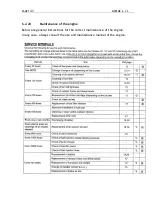
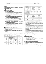
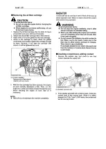
Page 143: ...PAGE 143 ALMAC s r l 6 2 20 Maintenance of the engine Below are general instructions for the correct maintenance of the engine In any case always consult the use and maintenance manual of the engine ...

Page 144: ...PAGE 144 ALMAC s r l ...

Page 145: ...PAGE 145 ALMAC s r l ...

Page 146: ...PAGE 146 ALMAC s r l ...

Page 147: ...PAGE 147 ALMAC s r l ...

Page 148: ...PAGE 148 ALMAC s r l ...

Page 149: ...PAGE 149 ALMAC s r l ...

Page 150: ...PAGE 150 ALMAC s r l ...

Page 151: ...PAGE 151 ALMAC s r l ...

Page 152: ...PAGE 152 ALMAC s r l ...

Page 153: ...mation must be of approximately 2 cm If the track sags and becomes too noisy as it moves it must be tightened as described below 1 Remove the guards 1 2 For proper track tension use a tensioning kit 2 not included and pump grease into the tensioning valve 3 until it reaches the pressure indicated below Consult the grease chart on the next pages for the type of grease required Max pressure for trac...

Page 154: ...replacing them when the tread is equal to or less than 10 mm The tracks must be changed even before they reach this limit if they are cuts or tears are noted Tracks must only be replaced by specialized properly trained personnel Follow the track replacement procedure illustrated on the following pages ...

Page 155: ...rmed people WARNING USE PERSONAL PROTECTIVE DEVICES Replacing the track The track must be replaced when 10 mm of tread is left or even earlier if there are any cuts Proceed as follows 1 Do not lift the machine from the ground excessively 15 20 cm are enough WARNING make sure that the machine is stable 2 Thoroughly clean all the parts of the undercarriage 3 Remove the side closure of the longeron 1...

Page 156: ...PAGE 156 ALMAC s r l 6 Using the nut supplied point A 7 Move the front wheel back by pressing on the track with your foot ...

Page 157: ...performing the tensioning of the track check the technical data sheet for the correct pressure expressed in bar 6 2 24 Track reduction gear oil level inspection Check the level of the oil in the track reduction gears at the frequencies given in the general chart Comply with the procedure described below HOW TO CHECK AND TOP UP THE REDUCTION GEAR OIL Before proceeding check the drawings below to fi...

Page 158: ...ow the reduction gear to turn a few times so as to eliminate any air pockets then check the various levels again Filling and level This reduction gear can be installed either horizontally or vertically HORIZONTAL INSTALLATION Figure 6 Pour oil into the reduction gear through the hole in pos 1 until it spills from the level holes in pos 2 or 4 then fit the plugs back in place VERTICAL INSTALLATION ...

Page 159: ...PAGE 159 ALMAC s r l ...

Page 160: ...ed to make it must be recovered for recycling purposes where possible Note ALMAC S r l declines all liability for damage to persons animals or things deriving from reuse of parts of the equipment for functions or assembly situations differing from the original ones Danger Machine decommissioning and demolition must be carried out only by properly trained and equipped personnel The machine must be ...

Page 161: ...or parts of it because the combustion products of plastic materials and paints could develop harmful polluting gases 7 3 Battery disposal Battery recycling is mandatory European Directive 2006 66 EC and recommended Cells and batteries even if fully discharged may still contain a considerable amount of energy It is therefore necessary to always protect the terminals to prevent short circuits Dispos...

Page 162: ...PAGE 162 ALMAC s r l 8 ATTACHMENTS 8 1 Declaration of conformity ...

Page 163: ...EC The purpose of this Register is to record events concerning the life of the machine in detail Mandatory routine inspections INAIL ASL authorized bodies Maintenance and obligatory inspections to check the integrity and structure of the machine and protection and safety systems Transfers of ownership to be notified to the competent INAIL former ISPESL department Supplementary maintenance or repla...

Page 164: ...PAGE 164 ALMAC s r l MANDATORY ROUTINE INSPECTIONS Date Observations Seal Signature ...

Page 165: ...necessary but should be made at least once a year when other operations are performed Type of inspection Description Visual and structural inspection Check the integrity of the anchors supports carpentry welding and pins Date Observations Signature 1st year 2nd year 3rd year 4th year 5th year 6th year 7th year 8th year 9th year 10th year NOTE frequency of the operation as indicated in the table in...

Page 166: ...hly registration is not necessary but should be made at least once a year when other operations are performed Type of inspection Description Grease the runners and wheels Date Observations Signature 1st year 2nd year 3rd year 4th year 5th year 6th year 7th year 8th year 9th year 10th year NOTE frequency of the operation as indicated in the table in Chapter 6 Monthly registration is not necessary b...

Page 167: ...y of the operation as indicated in the table in Chapter 6 Daily registration is not necessary but should be made at least once a year when other operations are performed Type of inspection Description Hydraulic reservoir oil change Date Observations Signature 1st year 2nd year 3rd year 4th year 5th year 6th year 7th year 8th year 9th year 10th year NOTE frequency of the operation as indicated in t...

Page 168: ...year 6th year 7th year 8th year 9th year 10th year NOTE frequency of the operation as indicated in the table in Chapter 6 Type of inspection Description Hydraulic filter replacement Date Observations Signature 1st year 2nd year 3rd year 4th year 5th year 6th year 7th year 8th year 9th year 10th year NOTE frequency of the operation as indicated in the table in Chapter 6 ...

Page 169: ...ar 8th year 9th year 10th year NOTE frequency of the operation as indicated in the table in Chapter 6 Type of inspection Description Check the operation of the Proactive levelling angle sensor Date Observations Signature 1st year 2nd year 3rd year 4th year 5th year 6th year 7th year 8th year 9th year 10th year NOTE frequency of the operation as indicated in the table in Chapter 6 ...

Page 170: ...r 8th year 9th year 10th year NOTE frequency of the operation as indicated in the table in Chapter 6 Type of inspection Description Check the operation of the electrical insulation monitoring device sentinel if present Date Observations Signature 1st year 2nd year 3rd year 4th year 5th year 6th year 7th year 8th year 9th year 10th year NOTE frequency of the operation as indicated in the table in C...

Page 171: ...equency of the operation as indicated in the table in Chapter 6 Type of inspection Description Engine oil inspection Date Observations Signature 1st year 2nd year 3rd year 4th year 5th year 6th year 7th year 8th year 9th year 10th year NOTE frequency of the operation as indicated in the table in Chapter 6 Daily registration is not necessary but should be made at least once a year when other operat...

Page 172: ...operation as indicated in the table in Chapter 6 Type of inspection Description Track inspection and tensioning Date Observations Signature 1st year 2nd year 3rd year 4th year 5th year 6th year 7th year 8th year 9th year 10th year NOTE frequency of the operation as indicated in the table in Chapter 6 Daily registration is not necessary but should be made at least once a year when other operations ...

Page 173: ...e operation as indicated in the table in Chapter 6 Type of inspection Description Track reduction gear oil level inspection Date Observations Signature 1st year 2nd year 3rd year 4th year 5th year 6th year 7th year 8th year 9th year 10th year NOTE frequency of the operation as indicated in the table in Chapter 6 Daily registration is not necessary but should be made at least once a year when other...

Page 174: ...icated in the table in Chapter 6 Registration every six months is not necessary but should be made at least once a year when other operations are performed Type of inspection Description Check the Proactive levelling redundancy valves Make sure that parking brake functions correctly when machine stops Date Observations Signature 1st year 2nd year 3rd year 4th year 5th year 6th year 7th year 8th ye...

Page 175: ...der balancing valves Make sure that parking brake functions correctly when machine stops Date Observations Signature 1st year 2nd year 3rd year 4th year 5th year 6th year 7th year 8th year 9th year 10th year NOTE frequency of the operation as indicated in the table in Chapter 6 ...

Page 176: ...Description of fault Solution Spare parts used Description Code qty Serious faults Date Description of fault Solution Spare parts used Description Code qty Serious faults Date Description of fault Solution Spare parts used Description Code qty ...

Page 177: ...characteristics and that variations if any have been recorded in the register Seller s business name Seller Purchaser Copy to send to ALMAC SRL on ownership of the MEWP serial no year of manufacture was transferred to It is hereby certified that as of the date above the technical dimensional and functional characteristics of the aforementioned platform conformed to the original characteristics and...

Page 178: ...PAGE 178 ALMAC s r l 8 4 Hydraulic diagram See attachment 8 5 Wiring diagram See attachment ...

Page 179: ...______________ 16 1 11 1 Intended use __________________________________________________________ 16 1 11 2 Improper uses_________________________________________________________ 18 1 11 3 Cases that relieve the manufacturer from liability ________________________ 18 2 SAFETY INFORMATION___________________________________________________________ 19 2 1 NOTIFICATION OF COMMISSIONING AND ROUTINE INSP...

Page 180: ...__________________ 61 3 4 3 Work platform height control device _______________________________________ 63 3 4 4 Load limiting device______________________________________________________ 64 3 5 HYDRAULIC SYSTEM SAFETY DEVICES ________________________________________________ 65 3 5 1 Hydraulic pressure limiting devices ________________________________________ 65 3 5 2 Hydraulic block safety device...

Page 181: ...upward movement of the work platform 97 4 2 5 2 Levelling in the transport configuration operating the manual controls ___________ 98 4 2 5 3 Dynamic Levelling during travel ______________________________________________ 99 4 2 5 4 Proactive Levelling__________________________________________________________ 99 4 2 6 Lifting descent of the work platform _____________________________________ 103 4 ...

Page 182: ...Suction filters replacement _________________________________________________ 129 6 2 10 2 Replacement of return filter ________________________________________________ 131 6 2 11 Checking the operation of the frame angle sensor ________________________ 132 6 2 12 Checking the operation of the scissor angle sensor _______________________ 133 6 2 13 Checking the operation of the Proactive levelling...

Page 183: ..._____________________ 162 8 2 REPORT REGISTER ____________________________________________________________ 163 8 3 PROPERTY TRANSFERS _________________________________________________________ 177 8 4 HYDRAULIC DIAGRAM __________________________________________________________ 178 8 5 WIRING DIAGRAM_____________________________________________________________ 178 9 INDEX ___________________________...

Reviews: