©
A
TL
A
g
ricu
ltu
ra
l
Te
ch
n
olog
y
L
imite
d:
S
e
pte
mbe
r
2
0
2
1
23
| Micro M5 Manual | v2.0
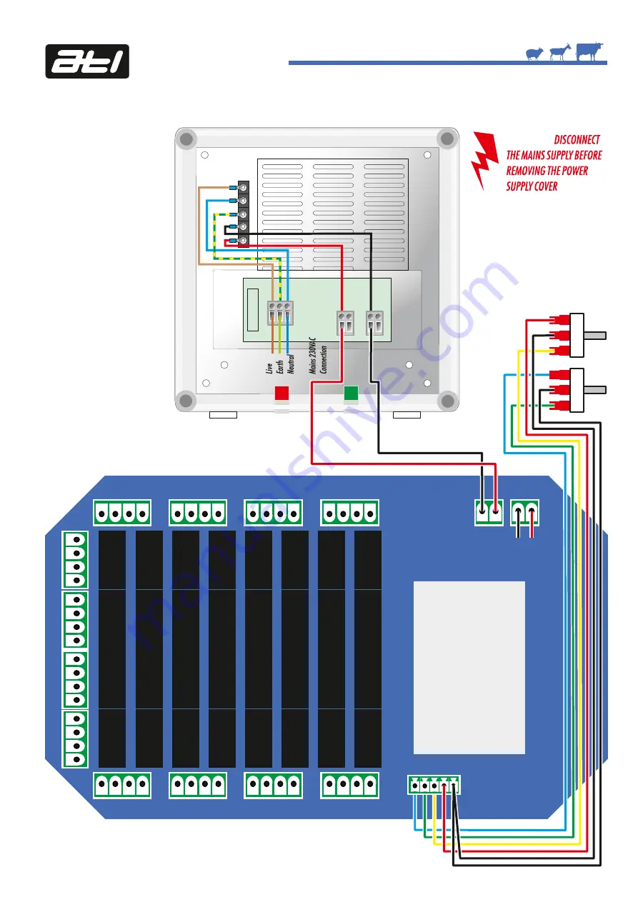
Wiring Diagram for Non-ATL Feeders and Control Only 60 Watt 12vDC Power Supply
MAINS
INDICATOR
MAINS
INPUT
OUTPUT
GLAND
OUTPUT
INDICATOR
IMPORTANT - OUTPUT FACTORY SET TO
14vDC TO ACCOUNT FOR VOLTAGE DROP
ALONG CABLE LENGTHS.
+
-
5Amp
Mains
Fuse
WARNING:
CONTROL
REGULATED DC
OUTPUTS NOMINAL
12vDC @ 4Amps
Innovation In and Out of Parlour
TO DISPLAY
PCB IN LID
NB - SEE POWER
SUPPLY MANUAL
FOR MORE
INFORMATION ON
POWER SUPPLY
SPECIFICATIONS
Feed
Mode
Switch
Standby
Switch
Feed Mode and
Standby Switch
Wiring
IMPORTANT -
Only 12vDC or
24vDC feeders can be powered
through the relay card


