background image

19 

ATIM_ACW-TMxP_UG_EN_V1.0 

the product transmits these frames both on the Sigfox network and in Local (FSK modulation). The FSK 
/ Sigfox repeater then relays these frames on the Sigfox network (The repeater must be placed in a 
location where the Sigfox network is accessible). 

Important note: If the product has access to the Sigfox network, the default operating mode (Sigfox) 
must be used. If this mode is chosen, the product will always send a frame on the Sigfox network 
and this same frame in Local mode to the Repeater, which will consume battery unnecessarily. 


Product’s clock


Each time you connect to the configurator, the product clock is updated (based on the computer clock) and displayed 
(

7

). In addition, an offset in seconds can be applied if needed. 


Versions of the product 

When connecting to the product, the configurator retrieves all the software versions of the product (product software 
and radio module software) as well as the network identifier (

8

). 


Temperature probes configuration 

On the ACW-TMxP, two temperature probes can be connected and configured (

9

). We find as a parameter: 

-


Activation / deactivation of the probe 

-


Choice of probe value (PT100 / PT1000) 

-


The type of probe wiring (2/4 or 3 wires) 

In addition, a threshold detection can be activated on each probe to detect a high or low threshold according to a 
configurable hysteresis and duration of overrun. When a measurement reaches a threshold, a radio frame will be sent 
(see the 

Alert Frame

 chapter for details on the frame format). 

Finally, temperature compensation can be applied to correct measurement errors (

10

) (changes in this compensation 

are directly visible on the temperature value which is sent back in real time by the product to the configurator). The 
compensation includes two setting points: a temperature offset as well as a multiplying coefficient. 


Digital input configuration 

The input can be configured according to the following parameters (

11

): 

-


The function of the input

: edge detection, counting or deactivation 

-


The type of pulling of the line: towards the mass or towards the supply 

-


The triggering edge

: rising, falling or both. 


In addition, it is possible to set a debounce time which corresponds to the wait after a change of level before taking it 
into account ("Input bounce time" in the configurator). 

Finally, when the input is configured for edge detection, and only in this mode, the current state of the input is shown 
on the right (under "Active level"). 


Summary of Contents for ACW/LW8-TM0P

Page 1: ...des Guillets 38250 Villard de Lans France www atim com info atim com ATIM Cloud Wireless Temperature monitoring through RTD TMxP User Guide Concerned models ACW LW8 TM1P ACW LW8 TM2P ACW LW8 TM0P ACW SF8 TM1P ACW SF8 TM2P ACW SF8 TM0P ...

Page 2: ...ATING MODE 12 B PRODUCT START UP 13 C TEST FRAME EMISSION 14 D DEEP SLEEP SETUP 14 E RADIO MODULE ACTIVITY 14 F THRESHOLD EXCEEDED 14 G ANTI FRAUD SYSTEM 14 H SUBSTITUTION TO THE MAGNET 14 I BATTERY PASSIVATION 15 ACW CONFIGURATOR 16 A COMPATIBLE CONFIGURATOR VERSION 16 B CONFIGURATION OF THE ACW TMXP 17 Emission period and samples in the frame 17 Keep alive frame period 17 Frame timestamp 18 Prod...

Page 3: ...uring frame 27 Alert measurement frame 28 DOWNLINK 29 A CONFIGURATION OF THE FRAME PARAMETERS SENDING PERIOD NUMBER OF SAMPLES ETC 29 B NUMBER OF PROBES 29 C TYPE OF PROBES 30 D THRESHOLD CONFIGURATION 30 E INPUT CONFIGURATION 30 F ANTI REBOUND CONFIGURATION 30 G RESERVED CODES FOR FUTURES EVOLUTIONS 31 TECHNICAL SUPPORT 32 ...

Page 4: ...ode modification YLB V0 0 1 0 8 24 06 2020 Documentation addition for the new input setup uplink and downlink frame AC V0 0 1 0 9 07 09 2020 Keep alive frame description AC V0 0 1 0 10 09 10 2020 Temperature probes features addition error code table modification AC V0 0 2 0 11 23 10 2020 Batteries passivation description AC V0 0 2 0 12 10 12 2020 Downlink datalogging frame description correction A...

Page 5: ...0 power 20mW or EN62311 2008 power 20mW 2 Electromagnetic Compatibility Article 3 1b of the 1999 5 EC Directive EN 301489 3 v1 4 1 EN 301489 1 V1 9 2 3 Efficient use of the radio frequency spectrum Art 3 2 of the 1999 5 EC Directive ETSI EN300 220 2 v2 4 1 and EN300 220 1 v2 4 1 Environmental recommendations a Explosive environment Except for the ACW ATEX range intended for this use do not use ACW...

Page 6: ...is symbol appears on a product or its packaging to indicate that the product may not be discarded with other household waste Rather it is your responsibility to dispose of this product by bringing it to a designated collection point for the recycling of electrical and electronic devices Collection and recycling waste separately at the time you dispose of it helps to conserve natural resources and ...

Page 7: ...4 4 Ah Weight 305 g Frequency 863 870 MHz Power 25 mW 14 dBm Rate Sigfox 100 bits s LoRaWAN 300 bit s à 10 Kbit s Consumption Sigfox LoRaWAN Tx mode 60 mA 55 mA IDLE 20 µA Rx mode 50 mA 25 mA Deep sleep mode 6 µA b Sensors functions Temperature Range 327 68 C to 327 67 C Resolution 0 05 C Precision from 25 C to 70 C Operating range 0 5 Data applicable to 2 wire probes supplied for TM1P and TM2P ve...

Page 8: ...8 ATIM_ACW TMxP_UG_EN_V1 0 Housing a Space requirements Maximum cable diameter through cable gland 7mm ...

Page 9: ...a DIN rail c Identification The Sigfox or LoRaWAN product identifier is visible on the exterior label on the back of the device on the electronic card inside and in the status bar in the ACW configuration tool For LoRaWAN modems the communication keys are automatically provided by the network pairing via Over The Air Activation or OTAA TMxP ACW TMxP label Product serial N Sigfox ID or LoRaWAN DevE...

Page 10: ...to Then pull on the back panel to separate the two parts of the housing e Installation Install the modem at least 2 m above the ground and not right against the wall ideally at least 20 cm away The cables must be no longer than 10 m and must be shielded For optimal results we recommend that you place it high up and at least 1 meter away from all metallic objects if possible see diagrams below Note...

Page 11: ...f 2 wire probes are used two jumpers should be placed on J1 and J2 above the 8 pin connector Without this the data reported by the product will be inconsistent Probe 2 A bis Probe 2 A Probe 2 B GND IN Probe 1 A bis Probe 1 A Probe 1 B Probe 2 A Probe 2 B GND IN Probe 1 A Probe 1 B T T T T ...

Page 12: ...nlink Network pairing mode This mode is active when the product exits deep standby mode and allows pairing to a network Fault mode This mode allows the normal operation of the module to be interrupted when a critical event occurs The nature of the event can be multiple Empty battery less than x of the minimum charge Error on the radio module Error when automated tests Error in the application Ente...

Page 13: ...d the information on network quality will then be relayed by the ACW light signal If no Downlink is provisioned the ACW will always display a WHITE light signal o If a WHITE light signal at the end of 5 minutes of the pairing phase is emitted by the product AND a Downlink has been provisioned this therefore means that the Network is not accessible o If a WHITE light signal at the end of the 5min p...

Page 14: ...olds have been configured using the configurator and the measurement values exceed these thresholds the product LED emits a periodic ORANGE flash to notify it g Anti fraud system A mechanism push button is present on the product to notify any opening of the case during normal operation Normally the box exerts pressure on the button As soon as the back cover is removed the button is released trigge...

Page 15: ...t the phenomenon of battery passivation during prolonged phases of deep standby This feature is automatically activated as soon as the product goes into its deep sleep mode The product will then wake up once a day to start the battery depassivation sequence then the product will automatically return to deep standby ...

Page 16: ...urator is launched the waiting window appears on the screen Click on Help at the top left of the window then on About to display the version number of the ACW configurator Pairing the ACW TMxP with the configurator can be done in two ways Through USB open the case of the ACW TMxP and connect it to a computer with a micro USB cable Through Bluetooth make sure that Bluetooth is activated Do not leav...

Page 17: ...ent will be made every 3 minutes and the 4 samples will be sent in a single frame every 12 minutes Finally it is possible to apply a redundancy of the data 3 which means that samples having been sent in the frame n 1 n 2 or n 3 could be sent again in the frame n to the continuation of the new measurement samples the most recent sample first in the frame and the least recent last For example for a ...

Page 18: ...k through this repeater In this mode if the network is not joined no JOIN_ACCEPT then the product will send its frames locally The LoRa LoRAWAN repeater then relays these frames on the network that it has joined the repeater must be placed at a location with connectivity to the desired network Important note If the product has access to the LoRAWAN network the default operating mode LoRaWAN Class ...

Page 19: ...f the probe Choice of probe value PT100 PT1000 The type of probe wiring 2 4 or 3 wires In addition a threshold detection can be activated on each probe to detect a high or low threshold according to a configurable hysteresis and duration of overrun When a measurement reaches a threshold a radio frame will be sent see the Alert Frame chapter for details on the frame format Finally temperature compe...

Page 20: ... product c Factory settings Radio frame settings Emission period of a radio frame 10 minutes Number of samplings 1 History depth 1 General settings Emission period of the keep alive frame 4 days Timestamp disabled Sensors settings Probe 1 State Enabled Type of probe PT100 Wiring 2 4 wires Threshold disabled Temperature calibration offset 0 coefficient 1 Probe 2 State Enabled Type of probe PT100 Wi...

Page 21: ...IM_ACW TMxP_UG_EN_V1 0 d Update of ACWs When connected with Bluetooth Low Energy to the product it is possible to update the different software that composes it To do this go to the menu Tools Updater CTRL U ...

Page 22: ...s of each of the channels that an ACW can read Beforehand the number of samples and the depth of the history will be inserted in the header Notes The number of samples and the depth of the history are in common for all the channels of the frame Alert frame threshold crossing New generation These frames combine a conventional frame and a measurement frame They consist of a header warning that a thr...

Page 23: ...sample of each of the alert channels 0x0e TBD General error TBD memory 0x0f Variable Subframe for ACW In function of the ACW product Measuring frame If the Timestamp is enabled 4 bytes with the Timestamp value will be preceded by the header byte 1 WARNING if Depth of history or Number of samplings is greater than 1 the frame emission period will be added after header byte 1 on two bytes Little End...

Page 24: ...the measurement sample s depending on the configuration of the product The number of bytes sent can be determined as follows Size in bytes of the measurement number of samples history depth Example For example for measurement type 0x08 the size of a value is two bytes with a history depth of 2 and 3 samples the size of the data to be read would be 12 bytes 2x2x3 WARNING a received temperature of 0...

Page 25: ...owing this header are 4 bytes 2 for the empty battery level and 2 for the charging battery level The frame is therefore split as follows 0xAABBBBCCCC 0xAA being the frame header always equal to 0x81 0xBBBB the empty battery level value in millivolts MSB coding and 0xCCCC the charging battery level value in millivolts MSB coding Example 0x81 0d24 0c68 0d24 empty battery level 3364 mV or 3 364 V 0c6...

Page 26: ...G_PERIOD Bad structure of sampling period 0x88 ERR_SUBTASK_END End of a sub task after leaving an infinite loop 0x89 ERR_NULL_POINTER Pointer with value NULL 0x8A ERR_BATTERY_LEVEL_DEAD Critical battery level 0x8B ERR_EEPROM EEPROM is corrupted 0x8C ERR_ROM ROM is corrupted 0x8D ERR_RAM RAM is corrupted 0x8E ERR_ARM_INIT_FAIL Radio module initialization has failed 0x8F ERR_ARM_BUSY The module is a...

Page 27: ...hannel 1 type of measurement temperature 0x28 0x21 The first sensor on channel 0 returns a value of 0x0885 21 81 C and the second sensor on channel 1 returns a value of 0x0850 21 28 C Now with 2 samples input disabled Byte 1 Byte 2 Byte 3 Byte 4 Byte 5 Byte 6 Byte 7 Byte 8 Byte 9 Byte 10 Byte 11 Byte 12 Byte 13 0xA1 new generation measureme nt frame no history 2 samples 0x003C emission period 0x08...

Page 28: ...surement temperature 0x08 0x85 0x18 channel 1 type of measurement temperature 0x08 0x50 The value of the counter is equal to 0x00000014 20 in decimal For temperature channel 0 the sample is 0x0885 21 81 C For temperature channel 1 the sample is 0x0823 20 83 C Alert measurement frame For a high threshold exceeded on channel 0 the frame will be Byte 1 Byte 2 Byte 3 Byte 4 0x8D new generation alert f...

Page 29: ...etc For byte 4 the two bits YY correspond to the history depth 1 max 3 and the three bits ZZZ correspond to the number of samples per frame 1 max 7 Bytes 5 and 6 correspond to the period for sending a frame 0xYYZZ ranging from 1 minute to 255 hours 15 300 minutes Example Byte 4 0x13 4 samples per frame addition of the four samples sent to the previous frame Byte 5 0x3C and byte 6 0x00 Sending peri...

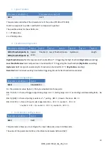
Page 30: ...iggering the low threshold Big Endian encoding Hysteresis field margin of uncertainty for thresholds in hundredths of C Big Endian encoding Duration field minimum waiting time before triggering the alert after threshold is exceeded e Input configuration Parameter code Byte 1 Byte 2 0x1B 0bAABB0CCC For the parameter value byte 2 the byte is divided into three parts Bits 7 6 AA choice of trigger edg...

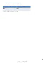
Page 31: ...31 ATIM_ACW TMxP_UG_EN_V1 0 g Reserved codes for futures evolutions Parameter code Byte 1 Parameter value Byte 2 0x10 0x08 0x11 0x00 WARNING DO NOT CHANGE THESE VALUES ...

Page 32: ...32 ATIM_ACW TMxP_UG_EN_V1 0 Technical support Contact our technical support team by email with any questions or technical problems you may have https www atim com en technical support ...

Reviews: