background image

AM2048A 

U S E R   G U I D E

ATL part no: 1/298/100/610
Issue 02 - Jan. 2003

Summary of Contents for AM2048A OS

Page 1: ...AM2048A U S E R G U I D E ATL part no 1 298 100 610 Issue 02 Jan 2003...

Page 2: ...V Maximum Current 170mA Power Rating Information AC Version Voltage Range 85Vrms to 250Vrms Maximum Current 20mA Frequency Range 50 60Hz TTE Network Safety Statements The AM2048A is a CLASS I product...

Page 3: ...V Safety Status Classification of non network PORTS Mains Input IEC320 85Vrms 250Vrms 50 60Hz connection has a safety status of PRIMARY CIRCUIT DC Input 3 PIN MINIFIT 40Vdc 75Vdc connection has a safe...

Page 4: ...6 T R A N S M I S S I O N P E R F O R M A N C E 3 3 5 C O M M I S S I O N I N G 3 1 4 ATL TELECOM USER GUIDE AM2048A 4 ATL TELECOM USER GUIDE AM2048A 5 7 5 2 X 21 39 7 5 3 V 35 40 7 5 4 e PIM 41 7 6...

Page 5: ...plies to the High Speed DSL product family designed and manufactured by ATL Telecom Limited in the U K It provides guidance for installation and commissioning of the products as well as useful referen...

Page 6: ...ay be configured to operate using one or two pairs A more economical single pair version is also available for applications where the flexibility of two pairs isn t necessary The AM2048 is available a...

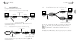
Page 7: ...3 X 21 V 35 10BaseT USB Master Slave Customer Terminal Customer Terminal AM2048A AM2048A G 703 X 21 V 35 10BaseT USB 1 or 2 copper pairs Master Slave ATL TELECOM USER GUIDE AM2048A 11 2 1 3 Desktop mo...

Page 8: ...female D type atl 3 C O N S T R U C T I O N 3 12 ATL TELECOM USER GUIDE AM2048A 2 1 4 Rack mount modem to desktop modem For customers with large installations at a central site the DSL shelf is avail...

Page 9: ...olour test sequence is displayed RED GREEN AMBER followed by the self test indication as follows Prior to the sequence starting a random pattern may appear momentarily User Master Test Local Loop Loop...

Page 10: ...he return key is pressed to accept the changes You will then be invited to log back on to the system 4 16 ATL TELECOM USER GUIDE AM2048A During sequence the available colours of each LED are displayed...

Page 11: ...d displays the appropriate screen in the Configuration User Port screen For X 21 and V 35 DTE DCE selection is carried out by moving the link header on the user interface plug in module The software a...

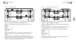
Page 12: ...al section at both ends are DTEs a clock inside the ELU then becomes the reference clock for the entire system AM2048 Slave AM2048 Master Terminal Terminal B B G 703 G 703 V 35 X 21 V 35 X 21 DTE DCE...

Page 13: ...andem Section External Timing For the following configurations the modems are connected in series with another transmission system or equipment that is the source of timing 4 9 2 1 X 21 V 35 DTE to X...

Page 14: ...work is shown where timing is passed transparently from end to end in both directions From a timing point of view this is equivalent to connecting Master A directly to Master B To provide a Master clo...

Page 15: ...SA5 SA6 SA7 SA8 FAW A SA4 SA5 SA6 SA7 SA8 FAW A SA4 SA5 SA6 SA7 SA8 4 26 ATL TELECOM USER GUIDE AM2048A 4 10 3 2 Structured Operation FIGURE 4 10 2 STRUCTURED WORKING END TO END TRANSPARENT CRCS To se...

Page 16: ...TELECOM USER GUIDE AM2048A 4 10 4 ETS 300 233 Loopbacks Loop 1 and Loop 2 may be activated by sending patterns using spare bits 5 and 6 in TS0 Table 1 CrC4 Multi frame Structure Sub Multi frame I II...

Page 17: ...egate line system The recording interval and the pass fail criterion of the datalog record are programmable by the user to match the tables found in ITU Recommendation M 2100 In the Performance Transm...

Page 18: ...oise Free Range on 0 4mm Wire 6 3 2 1 Pair Noise Free Range on 04mm Wire SPEED NOISE FREE RANGE ATTENUATION 2048kbps 4 4km 46 8dB 150kHz 1536kbps 4 75km 50 5dB 150kHz 1024kbps 5 3km 55 3dB 150kHz 768k...

Page 19: ...from ATL ATL Part Number See Appendix B CABLE AM2048A DC POWER 6 910 000 423 1 2 48V 0V 3 CGND 2 1 3 7 I N T E R F A C E S 7 34 ATL TELECOM USER GUIDE AM2048A 6 3 3 1 Pair With Noise Range on 04mm Wir...

Page 20: ...d Xon Xoff flow control The RS232C interface complies with the CCITT V24 V28 standards The maximum length of cable between communicating devices is limited to 15 2m 50ft Pin Function 1 2 Receive cct 1...

Page 21: ...Signal Element Timing Definition From DTE to DCE From DCE to DTE From DTE to DCE ON during Data OFF during Control From DCE to DTE ON during Data OFF during Control From DCE to DTE T and R change at O...

Page 22: ...o V 28 Circuit marked is only implemented in DTE mode The clock rate is set up using the Configuration User Port Menu Select the required value of N for Nx64K circuits DTE DCE mode may be selected usi...

Page 23: ...panel controls fully enabled as the default configuration This means that both test loop activation and modem programming are possible from the front panel They can however be disabled to prevent unau...

Page 24: ...AM2048A 45 8 44 ATL TELECOM USER GUIDE AM2048A 7 6 2 Indicators There are four tri colour LEDs that provide status information These are interpreted as follows The single colour LED indicators are int...

Page 25: ...e switch must be placed in the enable position for the modem to accept a new version of bootblock software FRONT Disable Enable ATL TELECOM USER GUIDE AM2048A 47 8 46 ATL TELECOM USER GUIDE AM2048A In...

Page 26: ...e function keys If you follow the installation of TeraTerm the function keys will be set up for you If the function keys cannot be programmed then you can type Control F followed by the number of the...

Page 27: ...M2048A Using the F8 function key check to see if the performance statistics are roughly the same for each line and for each end ELU and NTU of the line If there is a difference it could be that one en...

Page 28: ...SER GUIDE AM2048A Example results for 0 4mm gauge cable white gaussian noise Line will not train but I know the ELU and NTU are connected If an ELU running in two pair mode is connected to an NTU runn...

Page 29: ...nd the rate at which the stuff bits arrive is used to recover the user clock The transmit and receive paths may be operated independently from one another so that when a G 703 user interface is presen...

Page 30: ...TANDARDS The equipment is in conformity with the following Common Technical Regulations and National Standards Common Technical Regulations CTR2 X 21 X 21bis V 35 CTR12 G 703 2Mbps 120 unstructured CT...

Page 31: ...ELU and NTU DSP Digital Signal Processing DSL Digital Subscriber Line DTE Data Terminating Equipment E bit Bits in the G 704 frame used to indicate that a CRC has been received in error ELU Exchange...

Page 32: ...memory G 703 CCITT Recommendation G 703 1988 Physical electrical characteristics of hierarchical digital interfaces G 704 CCITT Recommendation G 704 1988 Synchronous frame structures user at primary a...

Page 33: ...between bits this will cause the link to error When in DCE mode the AM2048 provides two extra clocking options to work around this problem These options are accessed from the Configuration User Port s...

Page 34: ...TL TELECOM USER GUIDE AM2048A FIGURE A1 RECEIVE CLOCK INVERSION Clock Out Data Out DCE DTE Clock In Data In Data In Data Out Data clocked out on rising edge of the clock Data sampled on falling edge o...

Page 35: ...nterface V 35 Spare User Interfaces ATL part number Order Code G 703 2 298 001 1 298 001 X 21 2 298 002 1 298 002 V 35 2 298 003 1 298 003 e PIM 10 100BaseT 2 298 004 1 298 004 Accessories ATL part nu...

Page 36: ...rogramming Mode The front panel buttons and indicators are used as follows OPERATION The Local Loop and Loop Back buttons are used to programme the parameters Once programming is complete the Remote L...

Page 37: ...ntil AFTER the ELU has determined what type of user port the far end has The ELU will determine the user port of the far end automatically as soon as one transmission line has trained I e Line 1 or Li...

Page 38: ...1 0 1 00000 00001 00010 00011 00100 00101 00110 00111 No Off 75 Ohm No Off 120 Ohm No Off 75 Ohm No Off 120 Ohm Yes Off 75 Ohm Yes Off 120 Ohm Yes On 75 Ohm Yes On 120 Ohm 72 ATL TELECOM USER GUIDE A...

Page 39: ...and 5b Clamp refers to the C circuit for X21 interfaces and circuit 105 for V35 interfaces 3 In 5a and 5b these options must be set at the ELU and will be downloaded to the NTU They can t be changed...

Reviews: