Technical Manual & Parts Lists
12
rear edge guide. All five READY conditions should be good and you can now swipe the start switch
located below the screen.
The machine will sew up to the first corner, sew the first corner, then sew the next side up to the LAW
TAG insertion position and stop (if enabled). The operator then manually inserts the law tag and sews it
to the panel manually using the SEW pedal. Then swipe the start switch to resume automatic sewing.
The machine will sew around the next corner and stop at the LABEL insertion position (if enabled).
Manually sew the label to the panel and swipe the start switch again. The machine will continue sewing
around the panel until the first corner is about 12-18” in front of the foot. The machine will stop and the
flange will be cut. The machine will continue sewing and the front edge guide will shift in as the
previously sewn part of the first corner passes. As the trailing edge passes under the foot the needle
tension release will open allowing the machine to chain-off until the trailing edge passes the chain
cutting knife. The chain will be cut and the machine will either stop or feed at high speed to unload the
panel (depending on the setting of the UNLOAD mode on the operator screen). If the UNLOAD mode is
set to 1 the conveyor will continue to run at high speed until the CONVEYOR pedal is pressed. The
flange will automatically reinsert up to the presser foot.
Thread break detectors monitor all five sewing threads and will stop the machine if an error occurs. The
thread break monitors are named from left to right as Needle 1, Needle 2, Looper 1, Looper 2, and
Looper 3. Sewing can be resumed by pressing the CONTINUE button.
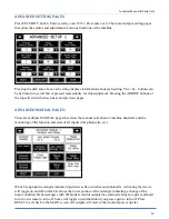
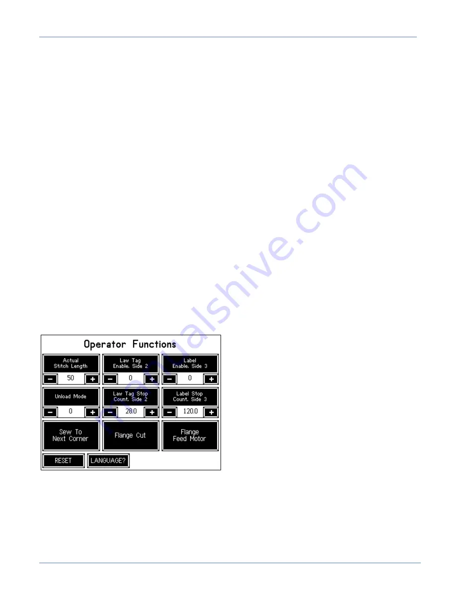
OPERATOR SCREEN:
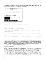
The Operator Screen allows the operator control of Law Tag and Label positions, and some manual
functions useful for managing the machine. Positions can be set as needed and each function can be
enabled or disabled as desired.
The UNLOAD mode can be selected (stop after cutting or continuous conveyor run). Flange Feed Motor
will feed flange without cutting. Flange Cut will cut the flange. There is also a setting called Actual
Stitch Length. This MUST be set to indicate the actual stitches-per-inch that the machine is sewing and
is used by the machine to control the corner sewing, conveyor synchronization, flange overlap, and
flange cut position. The resolution is in tenths of an inch – so 6.0 indicates six stitches per inch, 6.5
would be 6-1/2 stitches per inch, for example. The RESET button returns to the MAIN scree
Summary of Contents for 1317A
Page 2: ...Technical Manual Parts Lists 1 ...
Page 28: ...Technical Manual Parts Lists 23 ...
Page 30: ...Technical Manual Parts Lists 25 ...
Page 32: ...Technical Manual Parts Lists 27 ...
Page 34: ...Technical Manual Parts Lists 29 ...
Page 36: ...Technical Manual Parts Lists 31 ...
Page 39: ...Technical Manual Parts Lists 34 ...
Page 40: ...Technical Manual Parts Lists 35 ...
Page 42: ...Technical Manual Parts Lists 37 ...
Page 44: ...Technical Manual Parts Lists 39 ...
Page 48: ...Technical Manual Parts Lists 43 ...
Page 50: ...Technical Manual Parts Lists 45 ...
Page 51: ...Technical Manual Parts Lists 46 1318112 1 CONTROL PANEL AAC Drawing Number 1318112 Rev 2 ...
Page 52: ...Technical Manual Parts Lists 47 ...
Page 55: ...Technical Manual Parts Lists 50 ...
Page 56: ...Technical Manual Parts Lists 51 ...
Page 60: ...Technical Manual Parts Lists 55 ...
Page 63: ...Technical Manual Parts Lists 58 ...
Page 64: ...Technical Manual Parts Lists 59 ...
Page 71: ...Technical Manual Parts Lists 66 ...
Page 72: ...Technical Manual Parts Lists 67 ...
Page 79: ...Technical Manual Parts Lists 74 ...
Page 81: ...Technical Manual Parts Lists 76 ...
Page 83: ...Technical Manual Parts Lists 78 ...
Page 85: ...Technical Manual Parts Lists 80 1318356 CONVEYOR SUB ASSY 2 AAC Drawing Number 1318356 Rev 0 ...
Page 88: ...Technical Manual Parts Lists 83 ...
Page 89: ...Technical Manual Parts Lists 84 ...
Page 92: ...Technical Manual Parts Lists 87 ...
Page 93: ...Technical Manual Parts Lists 88 ...
Page 98: ...Technical Manual Parts Lists 93 ...
Page 100: ...Technical Manual Parts Lists 95 ...
Page 102: ...Technical Manual Parts Lists 97 ...
Page 104: ...Technical Manual Parts Lists 99 1317A PSM PROGRAM SETTINGS MAP ...
Page 105: ...Technical Manual Parts Lists 100 1317A WD WIRNG DIAGRAM CNTRL PNL ...
Page 106: ...Technical Manual Parts Lists 101 1317A PD PNEUMATIC DIAGRAM 1317A ...
Page 107: ...Technical Manual Parts Lists 102 ...


