Technical Manual & Parts Lists
17
Finishing the Frame
Swing out the folder and cut the gusset and flange. Raise the presser foot and
remove the frame. Be sure the stitches do not pull out as you remove the frame as the
starting and stopping stitch positions mark the seam location for finishing the frame.
Place the two ends of the frame together front to front with the starting and
stopping stitches on top of each other. Sew the ends together right across the stitch
position to complete the frame. Test fit the frame to a bed and adjust the thumbwheels as
necessary to achieve the best fit.
Adjust the ruffle size and stitches the same as in Panels mode.
Continental Foundations
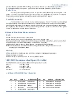
Continental foundations are made in the same way as the panels in Panels mode
except it requires the Large "M" style folder. Turn off the power and remove the regular
folder with the encoder on it by unplugging the encoder at the large 4 pin plug and
removing the two wing screws which hold the folder to the bracket. Protect the exposed
end of the plug with electrical tape to prevent accidental short circuit and damage to the
control box (The voltage at the plug is only 5 volts). Install the large folder with the slots
all the way to the left. Load the gusset material with the good side down at the presser
foot. Adjust the folder and edge guides for the stitch margin desired. Adjust the overhead
roller to keep the gusset aligned with the folder.
Continental foundations require smaller ruffles in the corners with more stitches per
ruffle. Adjust as necessary to achieve a desirable corner finish. Also, the stop count will be
a higher number due to the smaller stitch margin and will need to be adjusted for correct
stopping position.
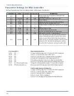
Efka Settings
The Efka control has been preprogrammed to operate the sewing head in
conjunction with the ruffler. The maximum sewing speed has been preset to 3500 RPM.
The maximum sewing speed can be temporarily reduced by holding in the "-" button on
front of the control box while sewing. To restore maximum speed use the "+" button. Be
sure the needle down LED (The second one from the bottom) is the only LED lit on front of
the control box. The LED's can be changed only immediately after power on or a full
healback. Refer to the appendix for complete Efka programming parameters.
Summary of Contents for 1335MDS
Page 2: ......
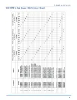
Page 27: ...Technical Manual Parts Lists 21 1335M Folder Spacer Reference Chart ...
Page 30: ...Technical Manual Parts Lists 24 ...
Page 32: ...Technical Manual Parts Lists 26 ...
Page 34: ...Technical Manual Parts Lists 28 ...
Page 36: ...Technical Manual Parts Lists 30 ...
Page 38: ...Technical Manual Parts Lists 32 ...
Page 40: ...Technical Manual Parts Lists 34 ...
Page 42: ...Technical Manual Parts Lists 36 ...
Page 44: ...Technical Manual Parts Lists 38 ...
Page 46: ...Technical Manual Parts Lists 40 ...
Page 48: ...Technical Manual Parts Lists 42 ...
Page 50: ...Technical Manual Parts Lists 44 ...
Page 52: ...Technical Manual Parts Lists 46 ...
Page 54: ...Technical Manual Parts Lists 48 ...
Page 56: ...Technical Manual Parts Lists 50 ...
Page 58: ...Technical Manual Parts Lists 52 ...
Page 60: ...Technical Manual Parts Lists 54 ...
Page 62: ...Technical Manual Parts Lists 56 ...
Page 66: ...Technical Manual Parts Lists 60 ...
Page 68: ...Technical Manual Parts Lists 62 ...
Page 70: ...Technical Manual Parts Lists 64 1335M 2400 Ball Screw and Nut Assembly 9000982 ...
Page 74: ...Technical Manual Parts Lists 68 ...
Page 76: ...Technical Manual Parts Lists 70 1335M PD Pneumatic Diagram 125618C ...
Page 77: ...Technical Manual Parts Lists 71 1335MDS PD Pneumatic Diagram 125670C ...
Page 78: ...Technical Manual Parts Lists 72 1335MDS WD Wiring Diagram 125650C ...
Page 79: ...Technical Manual Parts Lists 73 1335MDS WD1 Wiring Diagram 125573B ...
Page 80: ...Technical Manual Parts Lists 74 1335MDS WD2 Connection Diagram 125576B ...


