Technical Manual & Parts Lists
6
- Kinetic energy - Note that some motors or spindles, for example, may continue to run or coast run on
after being switched off.
- Potential energy - Individual assemblies may need to be secured if necessary for repair work.
Delivery of the Machine/Packaging
Note any markings on the packaging, such as weights, lifting points and special information. Avoid
temperature fluctuations. Condensation may damage the machine.
Transport Damage
The packaging and machine must immediately be examined for signs of damage in transit. Such damage
must be reported to the shipper/transporter within the applicable time limits. Contact Atlanta Attachment
Company and/or your transport insurer immediately, if signs of damage are visible. Never operate a
damaged machine.
Interim Storage
If the machine has to be stored temporarily, it must be oiled or greased and stored in a dry place where it
is protected from the weather in order to avoid damage. A corrosion-inhibiting coating should be applied
if the machine has to be stored for a longer period of time and additional precautions taken to avoid
corrosion.
Transporting the Machine
Disconnect the machine from all external connections and secure any loose assemblies or parts. Never
step under a suspended load. When transporting the machine or assemblies in a crate, ensure that the
ropes or arms of a forklift truck are positioned as close to the edge of the crate as possible. The center of
gravity is not necessarily in the middle of the crate. Note the accident prevention regulations, safety
instructions and local regulations governing transport of the machine and its assemblies.
Only use suitable transport vehicles, hoisting gear and load suspension devices that are in perfect
working order and of adequate carrying capacity. Transport should only be entrusted to duly qualified
personnel.
Never allow the straps to rest against the machine enclosure and never push or pull sensitive parts of the
machine. Ensure that the load is always properly secured. Before or immediately after loading the
machine, secure it properly and affix corresponding warnings.
All transport guards and lifting devices must be removed before the machine is started up again. Any
parts that are to be removed for transport must be carefully refitted and secured before the machine is
started up again.
Workplace Environment
Our machines are designed for use in enclosed rooms: Permissible ambient temperature approx. 5 - 40
°C (40 - 104 °F). Malfunctions of the control systems and uncontrolled machine movements may occur
at temperatures outside this range.
Protect against climatic influences, such as electrostatic charges, lightning strikes, hail, storm damage,
high humidity, salinity of the air in coastal regions.
Summary of Contents for 1335MDS
Page 2: ......
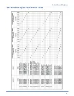
Page 27: ...Technical Manual Parts Lists 21 1335M Folder Spacer Reference Chart ...
Page 30: ...Technical Manual Parts Lists 24 ...
Page 32: ...Technical Manual Parts Lists 26 ...
Page 34: ...Technical Manual Parts Lists 28 ...
Page 36: ...Technical Manual Parts Lists 30 ...
Page 38: ...Technical Manual Parts Lists 32 ...
Page 40: ...Technical Manual Parts Lists 34 ...
Page 42: ...Technical Manual Parts Lists 36 ...
Page 44: ...Technical Manual Parts Lists 38 ...
Page 46: ...Technical Manual Parts Lists 40 ...
Page 48: ...Technical Manual Parts Lists 42 ...
Page 50: ...Technical Manual Parts Lists 44 ...
Page 52: ...Technical Manual Parts Lists 46 ...
Page 54: ...Technical Manual Parts Lists 48 ...
Page 56: ...Technical Manual Parts Lists 50 ...
Page 58: ...Technical Manual Parts Lists 52 ...
Page 60: ...Technical Manual Parts Lists 54 ...
Page 62: ...Technical Manual Parts Lists 56 ...
Page 66: ...Technical Manual Parts Lists 60 ...
Page 68: ...Technical Manual Parts Lists 62 ...
Page 70: ...Technical Manual Parts Lists 64 1335M 2400 Ball Screw and Nut Assembly 9000982 ...
Page 74: ...Technical Manual Parts Lists 68 ...
Page 76: ...Technical Manual Parts Lists 70 1335M PD Pneumatic Diagram 125618C ...
Page 77: ...Technical Manual Parts Lists 71 1335MDS PD Pneumatic Diagram 125670C ...
Page 78: ...Technical Manual Parts Lists 72 1335MDS WD Wiring Diagram 125650C ...
Page 79: ...Technical Manual Parts Lists 73 1335MDS WD1 Wiring Diagram 125573B ...
Page 80: ...Technical Manual Parts Lists 74 1335MDS WD2 Connection Diagram 125576B ...


