Technical Manual & Parts Lists
12
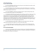
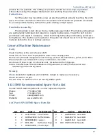
Top Six Thumbwheels:
The top six thumbwheels control the sewing of the panel when in Panels mode and also control
the ruffling in both Panels and Frames modes.
The first Thumbwheel on the left controls the on time of the Unwinder motor. It controls how
long the motor runs after the Loop Eye has seen the gusset material. It is usually set to 9. The lower the
number the less time the motor will run.
The second Thumbwheel controls the sewing speed of the sewing head during ruffling. Each
increment is approximately 100 rpm. The normal setting is "6".
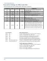
The third and fourth Thumbwheels together make up the Stop count for the corners when sewing
in Panel mode. This is the stitch count (00-99 stitches) from when the front eye uncovers until the
sewing stops in the corner to start the ruffling cycle. This should be adjusted to stop the panel so that
when the corner turn is finished the right edge of the panel is flush against the edge guide. If, after
turning the corner, the right edge of the panel is to the left of the edge guide, decrease the stitch count to
stop the panel sooner. If, after turning the corner, the right edge of the panel is to the right of the edge
guide, increase the stitch count to stop the panel closer to the foot.
The fifth Thumbwheel sets the number of ruffles to be sewn in each corner for both modes.
Adjust this setting along with the ruffle size to achieve desired corner finish.
The sixth Thumbwheel sets the number of stitches sewn in each ruffle for both modes and is
adjusted according to the ruffle size. There should be enough stitches to sew to the folded edge of each
ruffle.
Lower Six Thumbwheels:
The lower six thumbwheels control the sewing in Frames mode. The first three thumbwheels on
the left side set the length of the Short side of the Frame. The right three thumbwheels set the length of
the Long side. The resolution is in centimeters.
Summary of Contents for 1335MDS
Page 2: ......
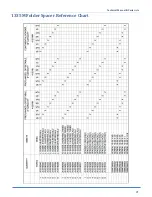
Page 27: ...Technical Manual Parts Lists 21 1335M Folder Spacer Reference Chart ...
Page 30: ...Technical Manual Parts Lists 24 ...
Page 32: ...Technical Manual Parts Lists 26 ...
Page 34: ...Technical Manual Parts Lists 28 ...
Page 36: ...Technical Manual Parts Lists 30 ...
Page 38: ...Technical Manual Parts Lists 32 ...
Page 40: ...Technical Manual Parts Lists 34 ...
Page 42: ...Technical Manual Parts Lists 36 ...
Page 44: ...Technical Manual Parts Lists 38 ...
Page 46: ...Technical Manual Parts Lists 40 ...
Page 48: ...Technical Manual Parts Lists 42 ...
Page 50: ...Technical Manual Parts Lists 44 ...
Page 52: ...Technical Manual Parts Lists 46 ...
Page 54: ...Technical Manual Parts Lists 48 ...
Page 56: ...Technical Manual Parts Lists 50 ...
Page 58: ...Technical Manual Parts Lists 52 ...
Page 60: ...Technical Manual Parts Lists 54 ...
Page 62: ...Technical Manual Parts Lists 56 ...
Page 66: ...Technical Manual Parts Lists 60 ...
Page 68: ...Technical Manual Parts Lists 62 ...
Page 70: ...Technical Manual Parts Lists 64 1335M 2400 Ball Screw and Nut Assembly 9000982 ...
Page 74: ...Technical Manual Parts Lists 68 ...
Page 76: ...Technical Manual Parts Lists 70 1335M PD Pneumatic Diagram 125618C ...
Page 77: ...Technical Manual Parts Lists 71 1335MDS PD Pneumatic Diagram 125670C ...
Page 78: ...Technical Manual Parts Lists 72 1335MDS WD Wiring Diagram 125650C ...
Page 79: ...Technical Manual Parts Lists 73 1335MDS WD1 Wiring Diagram 125573B ...
Page 80: ...Technical Manual Parts Lists 74 1335MDS WD2 Connection Diagram 125576B ...


