


Technical Manual & Parts Lists
16
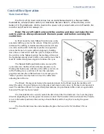
Basic Machine Operation (Frames Mode)
Setting the Switches
Switch the Panels / Frames switch to the Frames mode (down).
Note: The front photocell and the "stop count" thumbwheels have no
function in Frames mode.
Switch the Auto / Manual switch as desired. In Auto mode the machine will sew the
frame completely as long as you keep the sew pedal pressed. In Manual mode the
machine will stop at the start and end of each ruffle cycle and the sew pedal must be
released and pressed again.
Setting the Thumbwheels
Adjust the lower six thumbwheels to the Frame size desired. The size displayed on
the thumbwheels is in centimeters. Do to the corners and variations in material and other
factors it may be necessary to adjust the numbers to get the exact size frame desired. For
example: a test frame with an outside measurement of 150 x 203 was created with a
thumbwheel setting of 130 187. Create a chart to cross reference between the different
frame sizes and the actual numbers set in the thumbwheels.
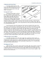
Loading the Flange Roll and Folder
Load the front roll holder with the flanging required and adjust the edge guides and
tension rods as necessary. Load the gusset through the folder, under the encoder roller,
and under the presser foot with at least 1" of material past the needle. Be sure the sensor
at the back of the swing-out bracket is lit indicating that the bracket is all the way in to
the detent. If the detent sensor is not lit, the machine will keep running without making
ruffles or measuring lengths.
Sewing the Frame
Press the Ruffle / Reset button twice to reset the program and prepare to start the
cycle.
Step on the sew pedal and the machine will sew the first half of a short side, make
a corner ruffle cycle, sew the first long side, make the second ruffled corner, sew the
opposite short side, make the third corner ruffle, make the opposite long side, ruffle the
last corner, and make the ending half short side. The machine will stop needle down and
will not sew any more until the presser foot is raised.
Summary of Contents for 1335MDS
Page 2: ......
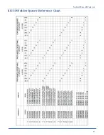
Page 27: ...Technical Manual Parts Lists 21 1335M Folder Spacer Reference Chart ...
Page 30: ...Technical Manual Parts Lists 24 ...
Page 32: ...Technical Manual Parts Lists 26 ...
Page 34: ...Technical Manual Parts Lists 28 ...
Page 36: ...Technical Manual Parts Lists 30 ...
Page 38: ...Technical Manual Parts Lists 32 ...
Page 40: ...Technical Manual Parts Lists 34 ...
Page 42: ...Technical Manual Parts Lists 36 ...
Page 44: ...Technical Manual Parts Lists 38 ...
Page 46: ...Technical Manual Parts Lists 40 ...
Page 48: ...Technical Manual Parts Lists 42 ...
Page 50: ...Technical Manual Parts Lists 44 ...
Page 52: ...Technical Manual Parts Lists 46 ...
Page 54: ...Technical Manual Parts Lists 48 ...
Page 56: ...Technical Manual Parts Lists 50 ...
Page 58: ...Technical Manual Parts Lists 52 ...
Page 60: ...Technical Manual Parts Lists 54 ...
Page 62: ...Technical Manual Parts Lists 56 ...
Page 66: ...Technical Manual Parts Lists 60 ...
Page 68: ...Technical Manual Parts Lists 62 ...
Page 70: ...Technical Manual Parts Lists 64 1335M 2400 Ball Screw and Nut Assembly 9000982 ...
Page 74: ...Technical Manual Parts Lists 68 ...
Page 76: ...Technical Manual Parts Lists 70 1335M PD Pneumatic Diagram 125618C ...
Page 77: ...Technical Manual Parts Lists 71 1335MDS PD Pneumatic Diagram 125670C ...
Page 78: ...Technical Manual Parts Lists 72 1335MDS WD Wiring Diagram 125650C ...
Page 79: ...Technical Manual Parts Lists 73 1335MDS WD1 Wiring Diagram 125573B ...
Page 80: ...Technical Manual Parts Lists 74 1335MDS WD2 Connection Diagram 125576B ...


