


Technical Manual & Parts Lists
19
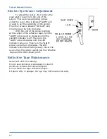
presser foot as possible. The ruffling air pressure should be set as high as practical
without it pressing the stripper blade down and pinching the panel while turning.
Puller Drive
Set the puller down position as low as practical without actually touching the cloth
plate. The roller should be centered on the needle. Set the Puller air pressure as needed
to provide positive feeding without the puller stalling at high speed.
Unwinder Assembly
The Unwinder is belt driven from a right angle gear motor. The motor and bearings
are permanently lubricated and require no regular maintenance. Check the belt tension
periodically and adjust if necessary. Check the timing belt pulley and bearing set screws
for tightness. The electric eye mounted on the guide rod should be set to "see" the gusset
material before the loop is entirely used up.
General Machine Maintenance
Daily
Clean machine at the end of every shift
Clean lint etc. from the Looper/bobbin area on the sewing head
Remove any threads wrapped around moving parts of the handwheel, puller, and ruffler.
Wipe all photo eye lenses with clean, nonabrasive, dry cloth
Use blow-off hose to get rid of excess lint, thread and other clippings
Follow manufactures recommendations and guidelines for daily maintenance and
lubricating of the sewing head.
Weekly
Check all belts for tightness and condition. Adjust or replace as necessary.
Check oil level in oil pan.
Put one drop of machine oil on all moving Ruffler parts.
11335MD Recommended Spare Parts List
Contact AAC’s sales department to order replacement parts.
Phone:
770-963-7369
Fax:
770-963-7641
Email:
sales@atlatt.com
Website:
www.atlatt.com
AAC Part # SP1335MD Spare Parts Kit
NO.
QTY
PART #
DESCRIPTION
NO.
QTY
PART #
DESCRIPTION
1
1
1278-7055B
Prox Switch
6
1
GG100XL037 Gear Belt
2
2
1335M-2002C Ruffler Blade
7
1
GG110XL75U Gear Belt
3
1
B2030481000 Looper
8
1
GG187L050
Gear Belt
4
2’
EEFE-RR2
Reflective Tape
9
100 SNTVX7X110 Needle
5
1
FFSM312LVQ Electric Eye
Summary of Contents for 1335MDS
Page 2: ......
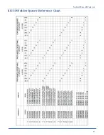
Page 27: ...Technical Manual Parts Lists 21 1335M Folder Spacer Reference Chart ...
Page 30: ...Technical Manual Parts Lists 24 ...
Page 32: ...Technical Manual Parts Lists 26 ...
Page 34: ...Technical Manual Parts Lists 28 ...
Page 36: ...Technical Manual Parts Lists 30 ...
Page 38: ...Technical Manual Parts Lists 32 ...
Page 40: ...Technical Manual Parts Lists 34 ...
Page 42: ...Technical Manual Parts Lists 36 ...
Page 44: ...Technical Manual Parts Lists 38 ...
Page 46: ...Technical Manual Parts Lists 40 ...
Page 48: ...Technical Manual Parts Lists 42 ...
Page 50: ...Technical Manual Parts Lists 44 ...
Page 52: ...Technical Manual Parts Lists 46 ...
Page 54: ...Technical Manual Parts Lists 48 ...
Page 56: ...Technical Manual Parts Lists 50 ...
Page 58: ...Technical Manual Parts Lists 52 ...
Page 60: ...Technical Manual Parts Lists 54 ...
Page 62: ...Technical Manual Parts Lists 56 ...
Page 66: ...Technical Manual Parts Lists 60 ...
Page 68: ...Technical Manual Parts Lists 62 ...
Page 70: ...Technical Manual Parts Lists 64 1335M 2400 Ball Screw and Nut Assembly 9000982 ...
Page 74: ...Technical Manual Parts Lists 68 ...
Page 76: ...Technical Manual Parts Lists 70 1335M PD Pneumatic Diagram 125618C ...
Page 77: ...Technical Manual Parts Lists 71 1335MDS PD Pneumatic Diagram 125670C ...
Page 78: ...Technical Manual Parts Lists 72 1335MDS WD Wiring Diagram 125650C ...
Page 79: ...Technical Manual Parts Lists 73 1335MDS WD1 Wiring Diagram 125573B ...
Page 80: ...Technical Manual Parts Lists 74 1335MDS WD2 Connection Diagram 125576B ...