Technical Manual & Parts Lists
20
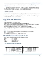
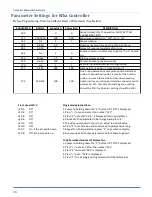
Parameter Settings for Efka Controller
Before Programming, Perform a Master Reset of Parameters (See Below)
PARAMETER
RANGE
Lockstitch
Chainstitch
DESCRIPTION
290
0
0
Mode (Lockstitch) of operation. MUST SET THIS
PARAMETER FIRST!
111
200-9900
400
400
Maximum speed when "129" is 0, 1, or 2.
161
0-1
1
1
Motor rotation
180
0-360
60
--
Degrees reverse run goes to get to needle up
181
0-999
1
--
Delay till reverse run starts after trim
182
0-1
1
0
Enable reverse run after trim to get to “true” needle
up
219
20363
35
35
Braking power at stop
250
0-359
150
--
Thread trimmer activation andle
270
0-5
1
1
External handwheel sensor configuration
271
0-255
180
180
Ref angle for Position 1 from Position 2
272
020-255
100
100
Drive ratio between motor pulley and handwheel
pulley. If handwheel pulley is smaller than motor
pulley, increase this value to slow down sewing
head until measured speed matches speed set with
parameter 111. (For Yamato and Pegasus, setting
should be 100; for Rimoldi, setting should be 124)
Front panel LED's:
Programming Instructions:
LED 1:
Off
1. Power on holding down the "P" button till "COD" is displayed.
LED 2:
Off
2. Press ">>" once and enter the number "311"
LED 3:
Off
3. Press "E" once and "2.0.0." is displayed this is a parameter
LED 4:
Off
4. Proceed to the parameter to be changed and press "E"
LED 5:
Off
5. The value now shows in the screen, adjust to desired value.
LED 6:
Off
6. Press "E" to enter value and continue with parameter setting.
LED 7:
On, Stop at needle down.
7. Repeat for other parameters, press "P" once when complete.
LED 8:
Off, Stop at needle up.
8. Run sewing head to save parameters before powering down
To Perform Master Reset of Parameters:
1. Power on holding down the "P" button till "COD" is displayed.
2. Press ">>" once and enter the number "591"
3. Press "E" twice and "093" is displayed.
4. Press "+" once, "094" is displayed.
5. Press "P" to exit programming mode with all default values.
Summary of Contents for 1335MDS
Page 2: ......
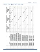
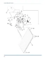
Page 27: ...Technical Manual Parts Lists 21 1335M Folder Spacer Reference Chart ...
Page 30: ...Technical Manual Parts Lists 24 ...
Page 32: ...Technical Manual Parts Lists 26 ...
Page 34: ...Technical Manual Parts Lists 28 ...
Page 36: ...Technical Manual Parts Lists 30 ...
Page 38: ...Technical Manual Parts Lists 32 ...
Page 40: ...Technical Manual Parts Lists 34 ...
Page 42: ...Technical Manual Parts Lists 36 ...
Page 44: ...Technical Manual Parts Lists 38 ...
Page 46: ...Technical Manual Parts Lists 40 ...
Page 48: ...Technical Manual Parts Lists 42 ...
Page 50: ...Technical Manual Parts Lists 44 ...
Page 52: ...Technical Manual Parts Lists 46 ...
Page 54: ...Technical Manual Parts Lists 48 ...
Page 56: ...Technical Manual Parts Lists 50 ...
Page 58: ...Technical Manual Parts Lists 52 ...
Page 60: ...Technical Manual Parts Lists 54 ...
Page 62: ...Technical Manual Parts Lists 56 ...
Page 66: ...Technical Manual Parts Lists 60 ...
Page 68: ...Technical Manual Parts Lists 62 ...
Page 70: ...Technical Manual Parts Lists 64 1335M 2400 Ball Screw and Nut Assembly 9000982 ...
Page 74: ...Technical Manual Parts Lists 68 ...
Page 76: ...Technical Manual Parts Lists 70 1335M PD Pneumatic Diagram 125618C ...
Page 77: ...Technical Manual Parts Lists 71 1335MDS PD Pneumatic Diagram 125670C ...
Page 78: ...Technical Manual Parts Lists 72 1335MDS WD Wiring Diagram 125650C ...
Page 79: ...Technical Manual Parts Lists 73 1335MDS WD1 Wiring Diagram 125573B ...
Page 80: ...Technical Manual Parts Lists 74 1335MDS WD2 Connection Diagram 125576B ...


