Technical Manual & Parts Lists
76
Atlanta Attachment Company (AAC) Statement of Warranty
Manufactured Products
Atlanta Attachment Company warrants manufactured products to be free from defects in material and
workmanship for a period of eight hundred (800) hours of operation or one hundred (100) days
whichever comes first. Atlanta Attachment Company warrants all electrical components of the Serial
Bus System to be free from defects in material or workmanship for a period of thirty six (36) months.
Terms and Conditions:
AAC Limited Warranty becomes effective on the date of shipment.
AAC Warranty claims may be made by telephone, letter, fax or e-mail. All verbal claims must be con-
firmed in writing.
AAC reserves the right to require the return of all claimed defective parts with a completed warranty
claim form.
AAC will, at its option, repair or replace the defective machine and parts upon return to AAC.
AAC reserves the right to make the final decision on all warranty coverage questions.
AAC warranty periods as stated are for eight hundred (800) hours or one hundred (100) days whichever
comes first.
AAC guarantees satisfactory operation of the machines on the basis of generally accepted industry
standards, contingent upon proper application, installation and maintenance.
AAC Limited Warranty may not be changed or modified and is not subject to any other warranty
expressed or implied by any other agent, dealer, or distributor unless approved in writing by AAC in
advance of any claim being filed.
What Is Covered
Electrical components that are not included within the Serial Bus System that fail due to defects in
material or workmanship, which are manufactured by AAC are covered for a period of eight hundred
(800) hours.
Mechanical parts or components that fail due to defects in material or workmanship, which are
manufactured by AAC.
Purchased items (sewing heads, motors, etc.) will be covered by the manufacturers (OEM) warranty.
AAC will assist in the procurement and handling of the manufacturers (OEM) claim.
What Is Not Covered
Parts that fail due to improper usage, lack of proper maintenance, lubrication and/or modification.
Damages caused by; improper freight handling, accidents, fire and issues resulting from unauthorized
service and/or personnel, improper electrical, plumbing connections.
Normal wear of machine and parts such as Conveyor belts, "O" rings, gauge parts, cutters, needles, etc.
Machine adjustments related to sewing applications and/or general machine operation.
Charges for field service.
Loss of time, potential revenue, and/or profits.
Personal injury and/or property damage resulting from the operation of this equipment.
Summary of Contents for 1335MDS
Page 2: ......
Page 27: ...Technical Manual Parts Lists 21 1335M Folder Spacer Reference Chart ...
Page 30: ...Technical Manual Parts Lists 24 ...
Page 32: ...Technical Manual Parts Lists 26 ...
Page 34: ...Technical Manual Parts Lists 28 ...
Page 36: ...Technical Manual Parts Lists 30 ...
Page 38: ...Technical Manual Parts Lists 32 ...
Page 40: ...Technical Manual Parts Lists 34 ...
Page 42: ...Technical Manual Parts Lists 36 ...
Page 44: ...Technical Manual Parts Lists 38 ...
Page 46: ...Technical Manual Parts Lists 40 ...
Page 48: ...Technical Manual Parts Lists 42 ...
Page 50: ...Technical Manual Parts Lists 44 ...
Page 52: ...Technical Manual Parts Lists 46 ...
Page 54: ...Technical Manual Parts Lists 48 ...
Page 56: ...Technical Manual Parts Lists 50 ...
Page 58: ...Technical Manual Parts Lists 52 ...
Page 60: ...Technical Manual Parts Lists 54 ...
Page 62: ...Technical Manual Parts Lists 56 ...
Page 66: ...Technical Manual Parts Lists 60 ...
Page 68: ...Technical Manual Parts Lists 62 ...
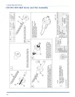
Page 70: ...Technical Manual Parts Lists 64 1335M 2400 Ball Screw and Nut Assembly 9000982 ...
Page 74: ...Technical Manual Parts Lists 68 ...
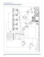
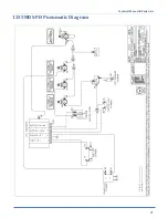
Page 76: ...Technical Manual Parts Lists 70 1335M PD Pneumatic Diagram 125618C ...
Page 77: ...Technical Manual Parts Lists 71 1335MDS PD Pneumatic Diagram 125670C ...
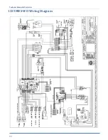
Page 78: ...Technical Manual Parts Lists 72 1335MDS WD Wiring Diagram 125650C ...
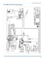
Page 79: ...Technical Manual Parts Lists 73 1335MDS WD1 Wiring Diagram 125573B ...
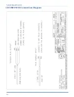
Page 80: ...Technical Manual Parts Lists 74 1335MDS WD2 Connection Diagram 125576B ...

