Technical Manual & Parts Lists
20
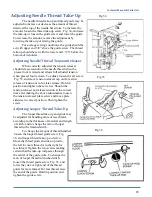
Fig. 13
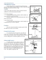
Alternating Presser with Pneumatic Pressure Control
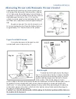
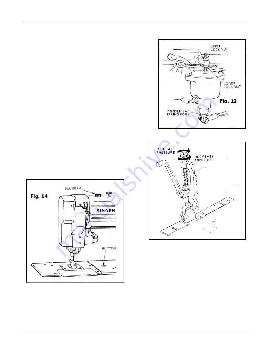
Adjust the height of the Pressure Cylinder with the presser
feet resting on the throat plate. There should be a clearance
of 1/4” between the Presser Bar Spring Fork and bottom of
the cylinder. To raise the cylinder, loosen the lower lock nut
and tighten upper lock nut, see Fig. 12. To lower the
cylinder, loosen the upper lock nut and tighten the lower lock
nut. When correct adjustment is attained, tighten both lock
nuts.
Regulate air pressure: The correct air pressure is set
for average feeding when the Presser Bar Spring Fork rises
to approximately 1/16” from the bottom of the cylinder.
Upper Feed Roll Pressure
To regulate the pressure of the upper feed roll,
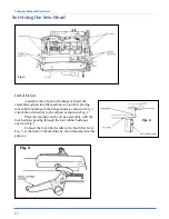
turn the thumb screw as shown in Fig. 13.
Stitch Length
To adjust the stitch length, depress the plunger,
Fig. 15, located on top of the arm. Continue to hold the
plunger down and turn the machine pulley toward the
operator until the plunger enters the notch in the arm
shaft eccentric. Then turn the plunger to lock in
position. Depress the button located on the machine bed. Hold down and turn the machine pulley toward
the operator to increase length of the stitch, or away from the operator to decrease the length of the
stitch. Letter “A” on the machine pulley indicates the lowest stitch. When desired length is indicated by
a letter and is opposite of the arrow on the front of the machine, release button and turn the plunger to
the right or left until it springs outward.
Caution: Never turn the machine pulley with the plunger in the locked position until the button on
the machine bed is depressed.
Summary of Contents for 1345-6A
Page 2: ...Technical Manual Parts Lists ...
Page 21: ...Technical Manual Parts Lists 14 ...
Page 36: ...Technical Manual Parts Lists 29 ...
Page 38: ...Technical Manual Parts Lists 31 ...
Page 40: ...Technical Manual Parts Lists 33 ...
Page 42: ...Technical Manual Parts Lists 35 ...
Page 44: ...Technical Manual Parts Lists 37 ...
Page 46: ...Technical Manual Parts Lists 39 ...
Page 48: ...Technical Manual Parts Lists 41 ...
Page 50: ...Technical Manual Parts Lists 43 ...
Page 52: ...Technical Manual Parts Lists 45 ...
Page 54: ...Technical Manual Parts Lists 47 ...
Page 56: ...Technical Manual Parts Lists 49 ...
Page 60: ...Technical Manual Parts Lists 53 ...
Page 66: ...Technical Manual Parts Lists 59 ...
Page 68: ...Technical Manual Parts Lists 61 ...
Page 70: ...Technical Manual Parts Lists 63 ...
Page 72: ...Technical Manual Parts Lists 65 ...
Page 74: ...Technical Manual Parts Lists 67 ...
Page 76: ...Technical Manual Parts Lists 69 ...
Page 78: ...Technical Manual Parts Lists 71 ...
Page 80: ...Technical Manual Parts Lists 73 ...
Page 82: ...Technical Manual Parts Lists 75 ...
Page 87: ...Technical Manual Parts Lists 80 1345 6WD1 Wiring Diagram ...

