Technical Manual & Parts Lists
24
Timing the Feed Lift Eccentric
When the feed dog is at its highest position, the top of the
teeth should be parallel with, and project full depth of the
teeth above the upper surface of the throat plate. To adjust,
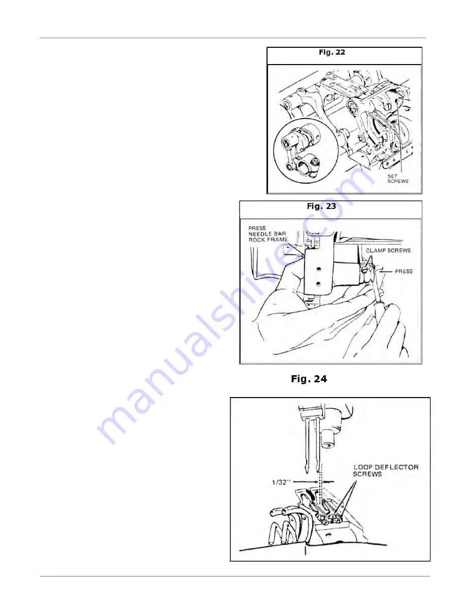
insert screwdriver in the hole in the feed strap and loosen
the two set screws, Fig. 22. Move the feed lift eccentric
forward for earlier rise of the feed dog, or backwards for
later rise. Then tighten the two set screws.
Needle Bar Positioning
The needles should enter the needle holes
of the feed dog toward the front with approximately
the same clearance between the front of the needles
and the front of the needle holes, and the side of the
needles to the side of needle holes. To adjust, press
the needle bar rock frame, Fig. 23, against the drive
arm clamp screws. Continue holding the rock frame
against the drive arm, move the needle bar to
correct the position and tighten the two clamp
screws.
Positioning the Loop Deflectors
When the loop deflector, located on the
underside of the feed dog, is positioned correctly,
there should be a clearance of approximately
1/32” between the right side of the needle and
loop deflector. To adjust, move the looper out
of sewing position and tilt the machine back on
its hinges. Loosen the loop deflector screws, Fig.
24. Move the deflectors toward the rear of the
feed dog as far as
the screw slots allow. Tighten slightly to allow
for further adjustment. Return the looper to the
sewing position and turn the machine pulley until
the needle bar has descended to the bottom of the
needle bar stroke. Tap the deflector to the left or
right until the correct clearance is attained. Move
the looper out of the sewing position and tighten
the loop deflector screws.
Summary of Contents for 1345-6A
Page 2: ...Technical Manual Parts Lists ...
Page 21: ...Technical Manual Parts Lists 14 ...
Page 36: ...Technical Manual Parts Lists 29 ...
Page 38: ...Technical Manual Parts Lists 31 ...
Page 40: ...Technical Manual Parts Lists 33 ...
Page 42: ...Technical Manual Parts Lists 35 ...
Page 44: ...Technical Manual Parts Lists 37 ...
Page 46: ...Technical Manual Parts Lists 39 ...
Page 48: ...Technical Manual Parts Lists 41 ...
Page 50: ...Technical Manual Parts Lists 43 ...
Page 52: ...Technical Manual Parts Lists 45 ...
Page 54: ...Technical Manual Parts Lists 47 ...
Page 56: ...Technical Manual Parts Lists 49 ...
Page 60: ...Technical Manual Parts Lists 53 ...
Page 66: ...Technical Manual Parts Lists 59 ...
Page 68: ...Technical Manual Parts Lists 61 ...
Page 70: ...Technical Manual Parts Lists 63 ...
Page 72: ...Technical Manual Parts Lists 65 ...
Page 74: ...Technical Manual Parts Lists 67 ...
Page 76: ...Technical Manual Parts Lists 69 ...
Page 78: ...Technical Manual Parts Lists 71 ...
Page 80: ...Technical Manual Parts Lists 73 ...
Page 82: ...Technical Manual Parts Lists 75 ...
Page 87: ...Technical Manual Parts Lists 80 1345 6WD1 Wiring Diagram ...

