Technical Manual & Parts Lists
51
A
B
4
5
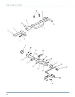
Installation of Footlift Link & Handle
Handle diagram is in the assemblies
Tools Required
(1) 7/16” wrench
(1) 7mm wrench
(1) 8mm wrench
(1) 9mm wrench
(1) 7/64” allen wrench
(1) 1/8” allen wrench
Installation
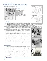
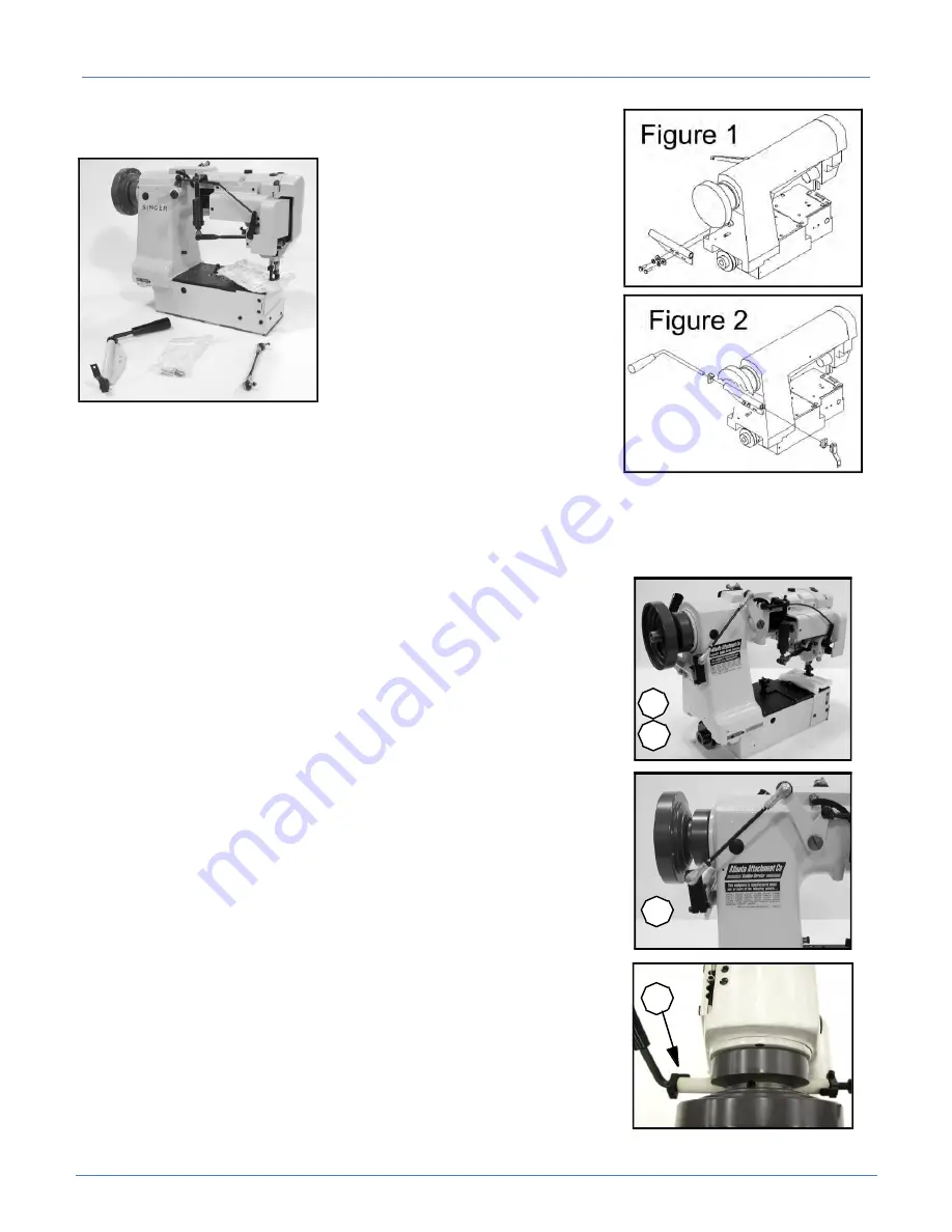
If not already installed, mount the pivot bracket (1345-503)
to the sewing head as shown using the 1/4-20 bolts and washers provided. Center the
slots on the bolts ensure the bracket is parallel to the sewing surface.
Place one stop collar (1345077) onto the pivot arm (1345-504) and insert the pivot arm
into the barrel of the pivot bracket as shown. Place another stop collar onto pivot arm
as shown.
Place the collar/link (1349518) on the pivot arm aligning the
two set screws in the collar with the two flat surfaces on
the pivot arm shaft. Tighten the two set screws.
Push the pivot arm until the collar/link is touching the
bearing surface on the pivot bracket. Then, snug the stop
collar, on the other side, against the other bearing surface
on the pivot bracket. Be sure the stop does not prevent
the handle from turning upwards approximately 90
degrees on the handle side.
Place one of the two threaded studs of the linkage (included
in accessory box) into the hole at the end of the
collar/link. Put the other threaded stud into the hole
located in the footlift lever. Place and tighten the two hex
nuts.
Adjustments
The following adjustments should be made to achieve
maximum footlift while the handle is able to stay in the up
position without being held.
Lengthen the linkage by turning the rod until the handle is
just able the stay in the up position. Tighten the lock nuts
on each end of the rod.
Turn the right stop collar until the stop hits the pivot bracket
in order to prevent the handle from turning more than is
necessary for it to stay in the up position.
Adjust the left stop collar so that the handle stops in the
down position.
Summary of Contents for 1345-6A
Page 2: ...Technical Manual Parts Lists ...
Page 21: ...Technical Manual Parts Lists 14 ...
Page 36: ...Technical Manual Parts Lists 29 ...
Page 38: ...Technical Manual Parts Lists 31 ...
Page 40: ...Technical Manual Parts Lists 33 ...
Page 42: ...Technical Manual Parts Lists 35 ...
Page 44: ...Technical Manual Parts Lists 37 ...
Page 46: ...Technical Manual Parts Lists 39 ...
Page 48: ...Technical Manual Parts Lists 41 ...
Page 50: ...Technical Manual Parts Lists 43 ...
Page 52: ...Technical Manual Parts Lists 45 ...
Page 54: ...Technical Manual Parts Lists 47 ...
Page 56: ...Technical Manual Parts Lists 49 ...
Page 60: ...Technical Manual Parts Lists 53 ...
Page 66: ...Technical Manual Parts Lists 59 ...
Page 68: ...Technical Manual Parts Lists 61 ...
Page 70: ...Technical Manual Parts Lists 63 ...
Page 72: ...Technical Manual Parts Lists 65 ...
Page 74: ...Technical Manual Parts Lists 67 ...
Page 76: ...Technical Manual Parts Lists 69 ...
Page 78: ...Technical Manual Parts Lists 71 ...
Page 80: ...Technical Manual Parts Lists 73 ...
Page 82: ...Technical Manual Parts Lists 75 ...
Page 87: ...Technical Manual Parts Lists 80 1345 6WD1 Wiring Diagram ...

