Manual & Parts Lists Technical
75
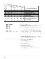
3.4.2 Stepping Motor Control Box
The stepping motor box is located under the table.
The Ruffler box has three thumbwheels on the front
which are set to synchronize the Ruffler to the sewing
head. The number is proportional to the stitch length
and is not affected by sewing speed. The 10
‐
turn
potentiometer is used to set the speed of the Ruffler
during the feed in to pleat and feed out to make the
next ruffle. It is set based on the thickness and type
of material being sewn, if the ruffler blade stalls
while feeding in or out you will need to lower the
setting on this control. To adjust unlock the dial and turn counter clockwise to reduce the speed turn
clockwise to increase.
The back of the box has an on/off switch, fuse, and
cables. Leave the on/off switch on all the time.
When working on the box always disconnect the
power cord before servicing.
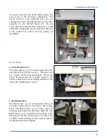
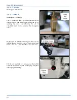
3.4.3.- AP-28-800Y1 Stepper Control Box
The Ruffler box is located under the table and has three Thumbwheels
“A”
on the front which
are set to synchronize the Ruffler to the sewing head. The number is proportional to the
stitch LENGTH and is not affected by sewing speed.
Original factory setting 108
The 10-turn potentiometer
“B”
is used to set the
speed of the Ruffler during the feed in to pleat and
feed out to make the next ruffle. It is
Pre-set to the
maximum 60 from the Factory
and is locked in
place by a small locking lever. Unlock to adjust.
A
B
Summary of Contents for 1335MD
Page 2: ......
Page 56: ...Manual Parts Lists Technical 49 2 7 1 Flow Chart Sizing Box Springs Page 1 ...
Page 58: ...Manual Parts Lists Technical 51 2 7 2 Flow Chart Cover Adjustments Page 2 ...
Page 99: ...Technical Manual Parts Lists 92 3 7 2 Flow Chart EFKA Error E1 ...
Page 105: ...Technical Manual Parts Lists 98 3 7 5 Flow Chart Stops at the corner ...
Page 106: ...Manual Parts Lists Technical 99 ...
Page 114: ...Manual Parts Lists Technical 107 ...
Page 116: ...Manual Parts Lists Technical 109 ...
Page 118: ...Manual Parts Lists Technical 111 ...
Page 120: ...Manual Parts Lists Technical 113 ...
Page 122: ...Manual Parts Lists Technical 115 ...
Page 124: ...Manual Parts Lists Technical 117 1335M 2400 Ball Screw Nut Assembly 9000982 ...
Page 125: ...Technical Manual Parts Lists 118 NOTES ...
Page 128: ...Manual Parts Lists Technical 121 ...
Page 132: ...Manual Parts Lists Technical 125 ...
Page 134: ...Manual Parts Lists Technical 127 ...
Page 136: ...Manual Parts Lists Technical 129 ...
Page 138: ...Manual Parts Lists Technical 131 ...
Page 140: ...Manual Parts Lists Technical 133 ...
Page 142: ...Manual Parts Lists Technical 135 ...
Page 144: ...Manual Parts Lists Technical 137 ...
Page 146: ...Manual Parts Lists Technical 139 ...
Page 148: ...Manual Parts Lists Technical 141 ...
Page 150: ...Manual Parts Lists Technical 143 ...
Page 152: ...Manual Parts Lists Technical 145 ...
Page 156: ...Manual Parts Lists Technical 149 ...
Page 158: ...Manual Parts Lists Technical 151 ...
Page 160: ...Manual Parts Lists Technical 153 ...
Page 162: ...Manual Parts Lists Technical 155 ...
Page 165: ...Technical Manual Parts Lists 158 1959 PD Pneumatic Diagram 125492C ...
Page 166: ...Manual Parts Lists Technical 159 1335MH PD Pneumatic Diagram 125586B ...
Page 167: ...Technical Manual Parts Lists 160 1335MF WD Wiring Diagram 125665C ...
Page 168: ...Manual Parts Lists Technical 161 1334S 02WD Wiring Diagram 125690C ...
Page 169: ...Technical Manual Parts Lists 162 1335MH 34WD Wiring Diagram 125186B ...
Page 170: ...Manual Parts Lists Technical 163 1335MH WD1 Wiring Diagram 125704C ...
Page 171: ...Technical Manual Parts Lists 164 ...


