3
Installation
TRION3 with Triton TR215CV Check Valve:
Install the TR215CV Triton Check Valve at the
appropriate discharge height by following the
instructions included with the product. Install
the union nut and 2” outlet fitting in accordance
to the Triton Check Valve instructions.
Attach the 2” outlet fitting on the Triton Check
Valve to the 2” spigot end of the electrode
chamber using PVC glue and cleaner to make
the connection. The Triton Ionizer can operate
with the electrodes facing in a vertical (up or down)
or horizontal direction and can be adjusted at any
time by loosening the union nut, twisting the
electrode chamber and re-tightening the
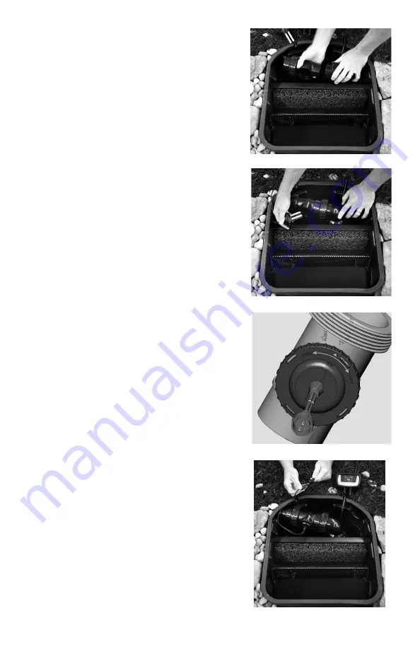
union nut. (Figure 1)
Attach the waterfall feed line to the 2” outlet of
the Triton Ionizer. If the waterfall feed line is 1½“
or smaller, replace the 2” outlet fitting on the
Triton Ionizer with the 1½” outlet fitting or stepped
adapter included with the Triton Check Valve. Use
PVC glue and cleaner to make the connection.
Install the electrodes into the electrode chamber.
The electrode body has a double O-ring to ensure
a watertight seal. Please inspect the electrodes
before installation to verify that both O-rings are
in place. (Figure 2)
Align the arrow on the top of the electrodes with
the word “align” on the electrode housing. Push
downward on the electrodes and turn in the “close”
or clockwise direction until the arrows align with
the electrode arrow pointing directly down the center
line of the Ionizer outlet. (Figure 3)
Mount the control panel in the desired location.
The control panel is weatherproof, but should be
mounted above the ground on a wall or post.
Ensure that the power cord is within reach of a
properly grounded GFCI outlet, and that the outlet
cord can reach the electrodes. Connect the outlet
cord to the electrodes and the power cord to the
supplied 12 volt AC transformer using the
quick-connect attachments. (Figure 4)
Figure 1
Figure 2
Figure 3
Figure 4


