F 7.2 3
F_7
.2_
01_G
B.
fm
3-
4
1.2
Points of maintenance
Track tightness (1)
m
Slack tracks may slip out of the guides of
the rolls, drive and guide wheels and in-
tensive wear may take place.
m
Too tight tracks add to the wear of guide wheels and drive bearings, the pins and
bushes of the tracks as well.
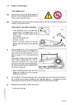
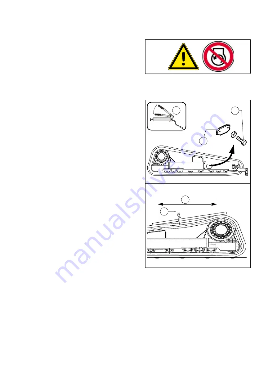
Track tension: checking / adjusting:
- Track tightness can be adjusted with
grease press. The filling ports are lo-
cated on the LH and RH sides of the
running gear.
- Remove the screws (A).
- Remove cap (B).
- Screw the head module of the flat
grease nipple (toolbox) on the grease
press.
A
Over a length (L) of 1-1.5 m, slack (F) of
2-3 cm must be present. This applies in
linear fashion if the free length (L) is less
than or equal to 1-1.5 m (at least 4 track
links).
The extent of slack in the track is estab-
lished using a measuring rule. This in-
volves the dimension (F) being mea-
sured from the edge of the baseplate to
the measuring rule (at the centrepoint of
the slack in the track).
- Keep pressing grease into the track
tightening cylinder until the required
tightness is achieved.
A
On completion of the tensioning process, the grease gun is removed. Now the trac-
tion unit should be moved backwards and forwards approx. 1 complete turn of the
drive wheel. Check the position of tracks on idler wheel and drive wheel.
A
Repeat this procedure on both drive units!
- Remount the lid (B).
LW_DEM2.bmp
x
B
A
Spann_LWDEM.bmp
B
L
F
Summary of Contents for DYNAPAC Svedala Demag DF 115 C
Page 2: ...VALUE QUALITY THE ORIGINAL Your Authorized Dynapac Dealer...
Page 10: ......
Page 18: ......
Page 20: ......
Page 44: ......
Page 58: ......
Page 62: ...D 1 4 4 D_1 4_01_GB fm 4 22 Element2_konv_Kette_635 bmp 9 12 9a 5 8 14 A 6 7 13...
Page 64: ...D 1 4 6 D_1 4_01_GB fm 6 22 Element2_konv_Kette_635 bmp 9 12 9a 5 8 14 A 6 7 13...
Page 96: ......
Page 120: ...D 4 6 24 D_4 6_01_GB fm 24 38 2 2 Error messages...
Page 121: ...D 4 6 25 D_4 6_01_GB fm 25 38...
Page 122: ...D 4 6 26 D_4 6_01_GB fm 26 38...
Page 123: ...D 4 6 27 D_4 6_01_GB fm 27 38...
Page 124: ...D 4 6 28 D_4 6_01_GB fm 28 38...
Page 125: ...D 4 6 29 D_4 6_01_GB fm 29 38 2 3 FMI codes...
Page 134: ......
Page 146: ...E 01 12 E_01_GB fm 12 18 3 Auger extension auger type II Auger_DEM bmp...
Page 152: ......
Page 154: ......
Page 157: ...F 3 0 1 F_3 0_01_GB fm 1 4 F 3 0 Maintenance Conveyor 1 Maintenance Conveyor...
Page 161: ...F 4 1 1 F_4 1_01_GB fm 1 8 F 4 1 Maintenance Auger 1 Maintenance auger sub unit...
Page 168: ......
Page 180: ......
Page 181: ...F 6 0 1 F_6 0_01_GB fm 1 8 F 6 0 Maintenance Hydraulic system 1 Maintenance hydraulic system...
Page 220: ......
Page 221: ...F 10 0 1 F_10 0_01_GB fm 1 6 F 10 0 Checks decommissioning 1 Tests check up cleaning stopping...
Page 226: ......

