background image

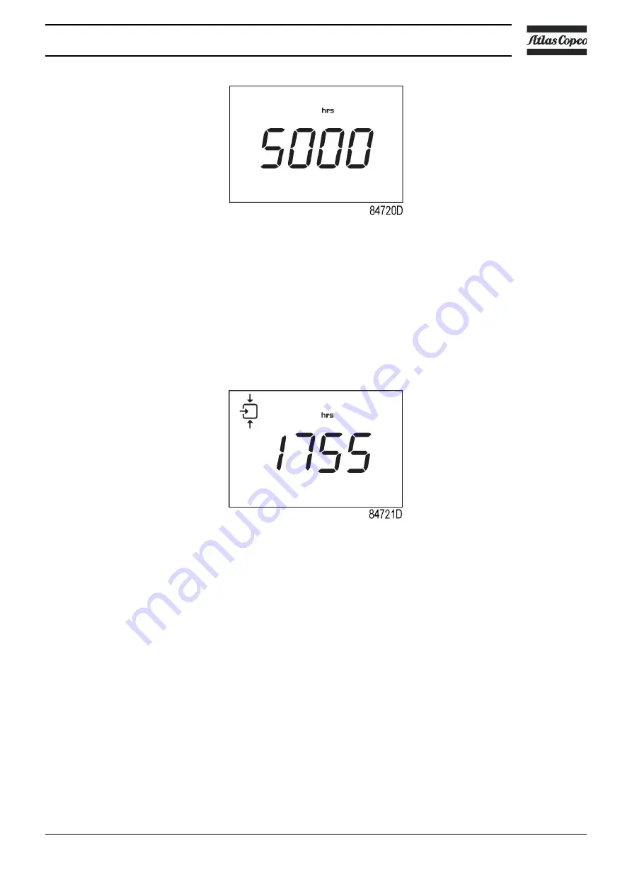
In the example shown, the screen shows the unit used <hrs> and the value <5000>: the
controller module has been in service during 5000 hours.

3.13 Calling up loading hours

Starting from the Main screen:

• Press Enter button (7) for 3 seconds to enter the Main menu.
• Select <dAtA> and press Enter button (7) to enter the Data menu.
• Scroll Up or Down buttons (4-8) until <d.4> and the running loaded symbol is shown.
• Press Enter button (7): the loading time is shown.

The screen shows the unit used <hrs> (or <x1000 hrs>) and the value <1755>: the compressor
has been running loaded during 1755 hours.

3.14 Calling up load solenoid valve

Starting from the Main screen:

• Press Enter button (7) for 3 seconds to enter the Main menu.
• Select <dAtA> and press Enter button (7) to enter the Data menu.
• Scroll Up or Down buttons (4-8) until <d.5> and the running loaded symbol is shown.
• Press Enter button (7): the number of loadings is shown.

Instruction book

2920 7119 21

39

Summary of Contents for G 15L

Page 1: ...INSTRUCTION BOOK OIL INJECTED ROTARY SCREW COMPRESSORS G 18 G 22 G 15L ...

Page 2: ......

Page 3: ... any part thereof is prohibited This applies in particular to trademarks model denominations part numbers and drawings This instruction book is valid for CE as well as non CE labelled machines It meets the requirements for instructions specified by the applicable European directives as identified in the Declaration of Conformity 2021 06 No 2920 7119 21 www atlascopco com ...

Page 4: ...SPOSAL 10 2 General description 11 2 1 INTRODUCTION 11 2 2 AIR FLOW 14 2 3 OIL SYSTEM 16 2 4 COOLING SYSTEM 17 2 5 REGULATING SYSTEM 18 2 6 CONTROL PANEL 19 2 7 ELECTRICAL SYSTEM 20 2 8 PROTECTION OF THE COMPRESSOR 22 2 9 AIR DRYER 23 3 Controller 24 3 1 CONTROLLER 24 3 2 CONTROL PANEL 25 3 3 ICONS USED ON THE DISPLAY 26 3 4 MAIN SCREEN 27 3 5 MAIN FUNCTION 28 3 6 SHUTDOWN WARNING 30 3 7 SHUTDOWN ...

Page 5: ...ALLING UP MODIFYING THE UNIT OF TEMPERATURE 41 3 19 CALLING UP MODIFYING THE UNIT OF PRESSURE 41 3 20 CALLING UP MODIFYING BACKLIGHT TIME 42 3 21 ACTIVATING AUTOMATIC RESTART AFTER VOLTAGE FAILURE 42 3 22 KEYBOARD LOCK 43 4 Installation 44 4 1 INSTALLATION PROPOSAL 44 4 2 DIMENSION DRAWINGS 46 4 3 ELECTRICAL CONNECTIONS 47 4 4 PICTOGRAPHS 50 5 Operating instructions 51 5 1 INITIAL START UP 51 5 2 ...

Page 6: ... 1 AIR FILTER 66 7 2 COOLERS 67 7 3 SAFETY VALVE 67 7 4 BELT SET EXCHANGE AND TENSIONING 68 7 5 DRYER MAINTENANCE INSTRUCTIONS 71 8 Problem solving 73 9 Technical data 76 9 1 ELECTRIC CABLE SIZE 76 9 2 SETTINGS FOR OVERLOAD RELAY AND FUSES 78 9 3 REFERENCE CONDITIONS AND LIMITATIONS 80 9 4 COMPRESSOR DATA 80 10 Instructions for use 82 11 Guidelines for inspection 83 Instruction book 4 2920 7119 21...

Page 7: ... the voltage Depressurize the machine Lock Out Tag Out LOTO Open the power isolating switch and lock it with a personal lock Tag the power isolating switch with the name of the service technician On units powered by a frequency converter wait 10 minutes before starting any electrical repair Never rely on indicator lamps or electrical door locks before maintenance work always disconnect and check w...

Page 8: ...let air 4 Any blanking flanges plugs caps and desiccant bags must be removed before connecting the pipes 5 Air hoses must be of correct size and suitable for the working pressure Never use frayed damaged or worn hoses Distribution pipes and connections must be of the correct size and suitable for the working pressure 6 In case the device is a compressor the aspirated air must be free of flammable ...

Page 9: ...m is present in the air net close to the dryer safety valves must be installed in the vessels of the dryer Also consult the following safety precautions Safety precautions during operation and Safety precautions during maintenance These precautions apply to machinery processing or consuming air or inert gas Processing of any other gas requires additional safety precautions typical to the applicati...

Page 10: ...amper with the sound damping material 12 Never remove or tamper with the safety devices guards or insulations fitted on the machine Every pressure vessel or auxiliary installed outside the machine to contain air above atmospheric pressure shall be protected by a pressure relieving device or devices as required 13 Yearly inspect the air receiver Minimum wall thickness as specified in the instructio...

Page 11: ...th open flame for inspecting the interior of a machine pressure vessel etc 14 Make sure that no tools loose parts or rags are left in or on the machine 15 All regulating and safety devices shall be maintained with due care to ensure that they function properly They may not be put out of action 16 Before clearing the machine for use after maintenance or overhaul check that operating pressures tempe...

Page 12: ...nts e g drain oil from oil containing parts 4 Refer to the disposal topic mentioned below Disposal of electrical and electronic appliances WEEE This equipment falls under the provisions of the European Directive 2012 19 EU on waste electrical and electronic appliances WEEE and may not be disposed as unsorted waste The equipment is labelled in accordance with the European Directive 2012 19 EU with ...

Page 13: ...he emergency stop button A cabinet housing the controller pressure sensor and motor starter is integrated into the bodywork Floor mounted model The compressor is installed directly on the floor Tank mounted model G 15L G 18 and G 22 tank mounted units are supplied with an air receiver of 500 l 132 US gal 110 Imp gal 17 5 cu ft Front view G 18 Full Feature tank mounted Reference Designation 1 Elect...

Page 14: ...ain DR Dryer D Dewpoint indicator only on Full Feature units DMS Dryer main switch only on Full Feature units Front open view G 18 Full Feature tank mounted Reference Designation Co Oil cooler OF Oil filter OS Oil separator OT Oil separator tank Instruction book 12 2920 7119 21 ...

Page 15: ...Rear open view G 18 Full Feature tank mounted Reference Designation Ca Air cooler E Compressor element AF Air filter Instruction book 2920 7119 21 13 ...

Page 16: ...drawn through filter AF and open inlet valve IV into compressor element E is compressed Compressed air and oil flow into oil separator tank OT The air is discharged via minimum pressure valve Vp and air cooler Ca towards the air outlet AO Instruction book 14 2920 7119 21 ...

Page 17: ... through filter AF and open inlet valve IV into compressor element E is compressed Compressed air and oil flow into oil separator tank OT The air is discharged via minimum pressure valve Vp air cooler Ca and air dryer DR towards the air outlet AO Instruction book 2920 7119 21 15 ...

Page 18: ... from the tank to compressor element E via oil cooler Co and oil filter OF Compressed air and oil flow into oil separator tank OT where most of the oil is separated from the air by centrifugal action The remaining oil is removed by oil separator OS and returns to the oil circuit via a separate line The minimum pressure Instruction book 16 2920 7119 21 ...

Page 19: ...y pass valve starts opening the supply from cooler Co when the oil temperature exceeds the setting of the valve The setting of the by pass valve depends on the model See section Compressor data 2 4 Cooling system Cooling system G 15L G 18 and G 22 Pack The cooling system of the Pack version comprises oil cooler Co and fan FN The fan mounted directly onto the motor shaft generates the cooling air i...

Page 20: ...nd fan FN The dryer DR of Full Feature versions has a separate cooling fan and an automatic condensate drain see also section Air dryer 2 5 Regulating system Detail view of unloader assembly UA The main components of the regulating system are Unloader UA including inlet valve IV and unloading valve UV Instruction book 18 2920 7119 21 ...

Page 21: ...troller that will stop the compressor after a variable period of unloaded operation using the following control algorithm At power on in the first work cycle the Unload period is 30 seconds After the first work cycle and in all other working cycles the Unload period is calculated following 3 rules a Given a maximum number of 10 restarts per hour factory setting the total running period per cycle L...

Page 22: ...ectric cabinet ER Elektronikon Base controller S3 Emergency stop button DMS Dryer Main Switch Only on Full Feature units 2 7 Electrical system Electrical components The electrical system comprises the following components Electric cubicle IEC Instruction book 20 2920 7119 21 ...

Page 23: ...tor overload relay K5 Auxiliary circuit relay K23 Delta contactor K21 Line contactor K11 Dryer relay only on Full Feature K22 Star contactor K25 Phase sequence relay PC Protection cover T1 Control transformer T2 Dryer transformer 1X0 Terminal block power supply X2 Terminal block of the control circuit 1X1 Terminal block voltage change of the motor only on tri voltage units 1XM Terminal block main ...

Page 24: ...und in the electric cubicle The complete electrical diagram can be found on the USB supplied with the machine 2 8 Protection of the compressor Safety valve on the compressor and on the vessel Reference Designation Function SV Safety valve To protect the air outlet system if the outlet pressure exceeds the opening pressure of the valve Instruction book 22 2920 7119 21 ...

Page 25: ...r then flows through heat exchanger 1 where refrigerant evaporates withdrawing heat from the air The cold air then flows through condensate trap 4 which separates condensate from the air The condensate is automatically drained The cold dried air then flows through heat exchanger 3 where it is warmed up by the incoming air Instruction book 2920 7119 21 23 ...

Page 26: ...ken into account e g the unloading and loading pressures the minimum stop time and the maximum number of motor starts The controller stops the compressor whenever possible to reduce power consumption and restarts it automatically when net pressure decreases If the expected unloading period is too short the compressor is kept running to prevent too short standstill periods Protecting the compressor...

Page 27: ...f the controller Service warning If the service timer exceeds the preset value the controller advises the operator via the display to carry out the service maintenance Automatic restart after voltage failure The controller has a built in function to automatically restart the compressor when the voltage is restored after voltage failure This function is deactivated on compressors leaving the factor...

Page 28: ...ds to enter in menu Use this button to confirm the last action Press 5 seconds to reset alarm 8 Scroll button Use these buttons to scroll through the menu 3 3 Icons used on the display Function Icon Description Stopped Running When the compressor is stopped the icon stands still When the compressor is running the icon is rotating Compressor status Motor stopped Running unloaded Running unloaded bl...

Page 29: ...isplayed NOTE x1000 ON if the displayed value is in thousands of hrs ON if the displayed value is in hours s ON if the displayed value is in seconds Element outlet temperature 3 4 Main screen At power on the first screen is a test screen Icon digit and led are on The next screen is the Main screen shown automatically The Main screen shows The compressor status by means of pictographs The air outle...

Page 30: ...erature of the element outlet Main screen with temperature stopped compressor 3 5 Main function To switch on the compressor press the start stop button 3 for 3 seconds The compressor starts and the status is shown Screen with running compressor To stop the compressor push the start stop button 3 The compressor unloads Instruction book 28 2920 7119 21 ...

Page 31: ... from the Main screen press the enter button 7 for 3 seconds The main menu is shown First screen of main menu It is possible to scroll in the menu with the up or down buttons 4 8 To select one item push the enter button 7 To end the current action push start stop 3 button If the emergency stop button is pushed the compressor stops immediately and the following screen will appear Instruction book 2...

Page 32: ...n warning will appear in the event of A too high temperature at the outlet of the compressor element Compressor element outlet temperature If the outlet temperature of the compressor element exceeds the shutdown warning level factory set at 110 C 230 F warning LED 5 is on Press Scroll up or down buttons 4 8 The screen shows the temperature at the compressor element outlet Instruction book 30 2920 ...

Page 33: ...of the compressor element exceeds the shutdown level detected by the temperature sensor or by the temperature switch In case of error of the outlet pressure sensor or temperature sensor In case of overload of the compressor motor In case of incorrect phase sequence detected by the phase sequence relay Compressor element outlet temperature If the outlet temperature of the compressor element exceeds...

Page 34: ...creen shows that the temperature at the outlet of the compressor element is 117 C When the shutdown condition has been solved press the Enter button 7 for 5 seconds When rSt appears on the display the compressor can be restarted Error pressure temperature sensor In the event of an error of the outlet pressure sensor PT20 or temperature sensor TT11 The compressor will stop The following screen will...

Page 35: ...motor overload Contact your supplier for fault troubleshooting When the shutdown condition has been solved press the enter button 7 for 5 seconds When rSt appears on the display the compressor can be restarted Incorrect phase sequence In the event of wrong phase sequence The compressor will not start Alarm LED 5 will flash The following screen will appear Instruction book 2920 7119 21 33 ...

Page 36: ...ice warning Description A service warning will appear when the service timer has reached the preset time interval If the service timer exceeds the programmed time interval alarm LED 6 is blinking with a following screen Blinking screen Press Enter button 7 to enter the main menu Select dAtA and press Enter button 7 to enter the data menu Scroll buttons 4 8 until d 6 and the service symbol is shown...

Page 37: ...hows that the service timer is at 2002 hours Stop the compressor switch off the voltage and carry out the required service actions After servicing reset the service timer See section Calling up resetting the service timer Instruction book 2920 7119 21 35 ...

Page 38: ...Main screen press the enter button 7 for 3 seconds to enter the Menu You will find the following items dAtA Data counters parameters ProG Submenu of Regulation pressure Timer Display setting and Control setting tESt Display test InFo Information of firmware release Instruction book 36 2920 7119 21 ...

Page 39: ...ning diSP Display tEMP Calling up or modifying unit of temperature PrES Calling up or modifying unit of pressure bC LG Calling up or modifying time of backlight Ctrl Control password required Lo rE Local remote start stop Ar Af Automatic restart after voltage failure Ar d Delay time of automatic restart after voltage failure nHCA Maximum number of compressor starts per hour PASS Activating passwor...

Page 40: ... dAtA and press Enter button 7 to enter the Data menu Scroll Up or Down buttons 4 8 until d 2 and the motor symbol is shown Press Enter button 7 the number of motor starts is shown This screen shows the number of motor starts x1 or if x1000 lights up x1000 In the above example the number of motor starts is 10100 3 12 Calling up module hours Starting from the Main screen Press Enter button 7 for 3 ...

Page 41: ...d the running loaded symbol is shown Press Enter button 7 the loading time is shown The screen shows the unit used hrs or x1000 hrs and the value 1755 the compressor has been running loaded during 1755 hours 3 14 Calling up load solenoid valve Starting from the Main screen Press Enter button 7 for 3 seconds to enter the Main menu Select dAtA and press Enter button 7 to enter the Data menu Scroll U...

Page 42: ...on 7 the service timer is shown This screen shows the unit used hrs or x1000 hrs and the value In the example shown the compressor has run 1191 hours since the previous service Reset can only be performed by authorized personnel Contact your supplier for further details 3 16 Calling up modifying pressure band selection Starting from the Main screen Press Enter button 7 for 3 seconds to enter the M...

Page 43: ... parameter The actual pressure used is shown Scroll Up or Down buttons 4 8 to set pressure value and press Enter button 7 to confirm The unit blinks and the new setting is saved 3 18 Calling up modifying the unit of temperature The unit of temperature measurement can only be changed when the compressor is stopped Starting from the Main screen Press Enter button 7 for 3 seconds to enter the Main me...

Page 44: ...lect ProG and press Enter button 7 to enter the Programming menu Scroll Up or Down buttons 4 8 to diSp for display settings Press Enter button 7 to enter the submenu Scroll Up or Down buttons 4 8 to bC LG and press Enter button 7 The current backlight setting is shown It is possible to set a value between 0s and 120s Scroll Up or Down buttons 4 8 to set the time of backlight and press Enter button...

Page 45: ...nds to lock or unlock the keyboard The display will show the label Loc blinking for 3 seconds if the keyboard has been locked The display will show the label UnLo blinking for 3 seconds if the keyboard has been unlocked Example Lock unlock screen Instruction book 2920 7119 21 43 ...

Page 46: ... if the ambient temperature can be below 0 C 32 F precautions must be taken In this case and also if operating at high altitude consult Atlas Copco Moving lifting Transport by a pallet truck For transport with a fork truck use the openings in the frame Move the compressor gently Instruction book 44 2920 7119 21 ...

Page 47: ...um distance between the wall and the back of the compressor is 300 mm 19 5 in 2 Position of the compressed air outlet valve Close the valve Connect the air net to the valve 3 The pressure drop over the air delivery pipe can be calculated as follows Δp L x 450 x Qc 1 85 d5 x P with d Inner diameter of the pipe in mm Δp Pressure drop in bar recommended maximum 0 1 bar 1 5 psi L Length of the pipe in...

Page 48: ...15L G 18 G 22 Full Feature floor mounted 9828 0837 53 G 15L G 18 G 22 Full Feature tank mounted Text on drawings Translation or explanation Emergency stop switch Emergency stop switch Power supply Power supply Cooling air and compressor inlet Cooling air and compressor inlet Cooling air outlet of compressor and motor Cooling air outlet of compressor and motor Service panel Service panel Compressor...

Page 49: ...ectric cable size for selection of power supply line cable Connect the power supply cables to terminals L1 L2 and L3 terminal block 1X0 and the neutral conductor if applicable to terminal N Connect the earth conductor to terminal PE GND Specific voltage change instructions for G 15L G 22 with 200 V 230 V 460 V cubicle The standard voltage configuration for the compressor is mentioned on the data p...

Page 50: ...2A fuses for 460V or 5A for 200V On Full Feature units replace the power fuses F7 with the CC type provided Use 12A for 460V and 25A for 200V 4 Modify the motor terminal bridge configuration in the cubicle 1X1 See further for details 5 Replace the voltage sticker by the appropriate voltage sticker provided Motor overload relay F21 setting Rotate the adjustment screw 1 on the front of the relay to ...

Page 51: ...A 5 A 2 A UL class JDYX or JDYX2 10 3 x 38mm 1 Fuse F7 only applicable to Full Feature units See also Electrical system for the service diagrams Motor terminal bridge configuration Factory standard connection is 230 V and can be changed to 200 V or 460 V Terminal bridges 1 can be removed using a pair of pliers Additional terminal bridges are provided with the compressor Voltage stickers Locate the...

Page 52: ...graphs Ref Description 1 Working pressure 2 Hour meter 3 Dew point temperature 4 Start 5 Stop 6 Warning voltage 7 Lightly oil gasket of oil filter screw filter on and tighten by hand 9 Warning switch off voltage and depressurise compressor before carrying out maintenance work Instruction book 50 2920 7119 21 ...

Page 53: ...rating instructions 5 1 Initial start up Safety The operator must apply all relevant Safety precautions General preparation Air outlet valve on air receiver Condensate drain Instruction book 2920 7119 21 51 ...

Page 54: ... close it and connect the air net to the valve Connect condensate drain valve Dm and automatic drain outlet Da to a drain collector Close the valve Connect condensate drain valve 4 of the air receiver to a drain collector Close the valve Oil system Oil level sight glass Step Action 1 Check the oil level Stop the unit and wait for the foam to disappear normally about 3 minutes The oil level should ...

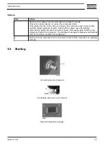
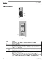
Page 55: ...ch off the voltage open the isolating disconnecter switch IG and reverse two phases of the supply cable Switch on the voltage and restart the compressor The shutdown message will disappear automatically when the shutdown condition has disappeared 2 Start and run the compressor for a few minutes Check that the compressor is operating normally 5 2 Starting Air outlet valve on air receiver Condensate...

Page 56: ...ting The maximum number of motor starts must be limited to 10 per hour It is strongly recommended to operate the compressor with a load factor of more than 10 to avoid condensate in the oil 5 Regularly check the oil level 10 to 15 minutes after stopping the oil should be visible through the sight glass SG If the oil level is too low stop the compressor depressurise the oil system by unscrewing oil...

Page 57: ...g unloading stopping of the motors and restarting 7 Regularly check the working pressure and the dew point Full Feature units 8 Regularly check that condensate is drained Da during operation 5 3 Stopping Air outlet valve Condensate drain valve on air receiver Control panel Instruction book 2920 7119 21 55 ...

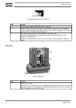
Page 58: ...an emergency Avoid using the button for normal stopping of the compressor 2 Close air outlet valve 2 and switch off the voltage to the compressor 3 Open condensate drain valve 4 of the air receiver for a few seconds to drain any condensate and then close the valve The air dryer and the air receiver remain under pressure The integrated filter if installed remains pressurised If maintenance or repai...

Page 59: ...mains 3 Depressurize the compressor by opening plug 3 one turn Open condensate drain valve Dm Open condensate drain valve 4 of the air receiver 4 Shut off and depressurize the part of the air net which is connected to the outlet valve Disconnect the compressor from the air net 5 Drain the oil and condensate circuits 6 Disconnect the compressor condensate outlet and valve from the condensate net In...

Page 60: ... maintenance schedule especially the service intervals depending on the environmental and working conditions of the compressor The longer interval checks must also include the shorter interval checks Preventive maintenance schedule Period 1 Running hours 1 Action Daily Check the oil level After stopping drain the condensate from the air receiver by means of the manual drain valve 4 see section Sto...

Page 61: ... instrument block Thermostatic and MPV kit 8000 Check and clean the inlet valve Use the unloader kit 8000 Replace the belts 1 whichever comes first 2 more frequently in a dusty environment 3 The indicated oil exchange intervals are valid for standard operating conditions see section Reference conditions and limitations and nominal operating pressure see section Compressor data Exposure of the comp...

Page 62: ...12 F 3000 1 year from 35 C 95 F up to 40 C 104 F see note from 100 C 212 F up to 105 C 221 F 2000 1 year above 40 C 104 F above 105 C 221 F use Roto Synthetic Fluid XTEND DUTY Note The presence of dust and or high humidity may require a shorter exchange interval Consult Atlas Copco Atlas Copco s Roto Inject Fluid Ndurance is a premium mineral oil based 4000 hours lubricant specially developed for ...

Page 63: ...o Synthetic Fluid XTEND DUTY Exchange interval for Roto Synthetic Xtend Duty Ambient temperature Element outlet temperature Exchange interval Maximum time interval up to 35 C 95 F up to 100 C 212 F 8000 2 years from 35 C 95 F up to 40 C 104 F see note from 100 C 212 F up to 105 C 221 F 6000 2 years above 40 C 104 F above 105 C 221 F 5000 2 years Note The presence of dust and or high humidity may r...

Page 64: ...ricant keeps the compressor in excellent condition Roto Foodgrade Fluid can be used for compressors operating at ambient temperatures between 0 C 32 F and 40 C 104 F Roto Foodgrade Fluid has all required certification for use in food beverage industry like NSFH1 Kosher Halal and Allergen Free approvals 6 4 Oil filter and separator change Important Never mix oils of different brands or types A labe...

Page 65: ... gets into the system 8 Refit and tighten filler plug 2 9 Close drain valve 8 of the air receiver 10 Run the compressor for a few minutes 11 Stop the compressor and wait a few minutes to allow the oil to settle 12 If the oil level is too low depressurize the system by unscrewing filler plug 2 one turn to permit any pressure in the system to escape Depressurize the air receiver by opening drain val...

Page 66: ...efit and tighten filler plug 2 8 Close drain valve 8 of the air receiver 9 Run the compressor for a few minutes 10 Close the front panel 6 5 PDX DDX filter change option Oil filler plug Drain valve air receiver Step Action 1 Stop the compressor close the air outlet valve switch off the voltage and depressurise by unscrewing oil filler plug 3 one turn to permit any pressure in the system to escape ...

Page 67: ...ve measures may be necessary 6 7 Service kits Service kits For overhauling and for preventive maintenance a wide range of service kits is available Service kits comprise all parts required for servicing the component and offer the benefits of genuine Atlas Copco parts while keeping the maintenance budget low Also a full range of extensively tested lubricants suitable for your specific needs is ava...

Page 68: ...t valve and switch off the voltage Open the isolating disconnector switch IG 2 Remove the front panel and the top panel of the compressor housing 3 Unscrew the filter cover AF and remove the filter element Discard the air filter element 4 Fit the new element and screw on the filter cover 5 Refit the top and front panels Instruction book 66 2920 7119 21 ...

Page 69: ...Stop the compressor close the air outlet valve and switch off the voltage Remove any dirt from the oil cooler Co with a fibre brush Open the isolating disconnector switch IG Also remove any dirt from the air cooler Ca Never use a wire brush or metal objects Then clean using an air jet 7 3 Safety valve Condensate drain valve Instruction book 2920 7119 21 67 ...

Page 70: ...ves 4 tank mounted units and the manual drain valve 5 if fitted on floor mounted units and unscrew filler plug 3 one turn to permit any pressure in the system to escape If the valve does not open at the set pressure stamped on the valve replace the valve No adjustments are allowed Never run the compressor without a safety valve 7 4 Belt set exchange and tensioning Read the warning in the Preventiv...

Page 71: ...measured are indicated with a label 1 on the frame 4 Refit the bodywork panels Tensioning of the belts must be performed with specific dedicated tooling Adjusting the tension of the drive belts Step Action 1 Stop the compressor close the air outlet valve and switch off the voltage Open the isolating disconnector switch IG 2 Remove the front door the internal panel the top cover and the pulley prot...

Page 72: ... with the power of the unit and with the total running hours of the belt The values to be measured are indicated with a label 1 on the frame 6 Retighten bolts 2 7 Refit the bodywork panels Replacing the drive belts Instruction book 70 2920 7119 21 ...

Page 73: ...s must be observed Please be specifically aware of the following points Contact of refrigerant with the skin will cause freezing Special gloves must be worn If contacted with the skin the skin should be rinsed with water On no account may clothing be removed Fluid refrigerant will also cause freezing of the eyes always wear safety glasses Refrigerant is harmful Do not inhale refrigerant vapours Ch...

Page 74: ...e Remove the panel where the condenser is situated see the picture below Clean the condenser fins with compressed air Do not use water or solvents Close the panel Inspect and clean the electronic condensate drain monthly Functioning of the drains can be checked by pushing the TEST button of the drain Cleaning of the drain filter can be done by opening the manual drain valve during a few seconds In...

Page 75: ...8 Problem solving Control panel Air outlet valve Oil filler plug Instruction book 2920 7119 21 73 ...

Page 76: ...ows Close the valve Remove the screw fixing the handle Remove the handle Fit the screw Faults and remedies For all references given hereafter see Air flow diagram Initial start up or Regulating system Condition Fault Remedy 1 Compressor starts running but does not load after a delay time Solenoid valve Y1 out of order Replace valve Inlet valve IV stuck in closed position Have valve checked Leak in...

Page 77: ...perature too high Check for cooling air restriction or improve ventilation of compressor room Avoid recirculation of cooling air If installed check capacity of compressor room fan Oil level too low Check and correct as necessary Cooler clogged Clean cooler Compressor element E out of order Consult Atlas Copco Instruction book 2920 7119 21 75 ...

Page 78: ...the supply cable to the compressor Local regulations remain applicable if they are stricter than the values proposed below IEC versions For IEC designed control panels the below suggested cable sections are calculated according to EN60364 5 52 Electrical installations of buildings selection and erection equipment current carrying capacities in wiring systems Standard conditions refer to Multi core...

Page 79: ...er cables If the local conditions are more severe then the described standard conditions the cables for worst case conditions should be used Recommended cable size Pack version PVC 70 C XLPE EPR 90 C G 15L G 18 G 22 Frequency Hz Voltage V Cable size Cable size Cable size IEC 50 230 25 mm2 16 mm2 50 mm2 25 mm2 70 mm2 35 mm2 50 400 10 mm2 10 mm2 16 mm2 10 mm2 25 mm2 16 mm2 60 230 25 mm2 16 mm2 50 mm...

Page 80: ... gL is also allowed For UL designed machines calculations of fuses are done according to UL508A Industrial control panels For CSA calculations of fuses are done according to CSA 22 2 Canadian electrical code Fuse size is the maximum fuse size in order to protect the motor against short circuit For CSA fuse HRC form II For UL fuse class J or RK5 If the local conditions are more severe then the desc...

Page 81: ...y FM1 A Fuses FU aM gG Overload relay FM1 A Fuses FU aM gG Overload relay FM1 A Fuses FU aM gG 50 230 36 0 80A 80A 43 5 100A 100A 50 4 100A 125A 50 400 20 6 50A 50A 25 2 50A 63A 29 0 63A 80A 60 380 21 7 40A 50A 25 9 50A 63A 30 5 63A 80A 60 460 18 3 40A 40A 22 1 40A 50A 25 9 50A 63A CSA UL Overload relay FM1 A FU Main fuses A class J or RK5 Disc Switch IG size 1 25 x FLA see conn Diagram Overload r...

Page 82: ... psi 150 psi 175 psi 7 5 bar 10 bar 13 bar Frequency Hz 60 60 60 60 50 50 50 Maximum unloading pressure UL units bar 7 4 9 1 10 8 12 6 7 50 10 13 Maximum unloading pressure UL units psig 107 132 157 182 109 145 189 Nominal working pressure bar 6 9 8 6 10 3 12 1 7 0 9 5 12 5 Nominal working pressure psig 100 125 150 175 102 138 181 Set point thermostatic valve C 60 60 60 60 60 60 60 Set point therm...

Page 83: ... 125 psi 150 psi 175 psi 7 5 bar 10 bar 13 bar Frequency Hz 60 60 60 60 50 50 50 Maximum unloading pressure UL units bar 7 4 9 1 10 8 12 6 7 50 10 13 Maximum unloading pressure UL units psig 107 132 157 182 109 145 189 Nominal working pressure bar 6 9 8 6 10 3 12 1 7 0 9 5 12 5 Nominal working pressure psig 100 125 150 175 102 138 181 Set point thermostatic valve C 60 60 60 60 60 60 60 Set point t...

Page 84: ...rtheless a weekly check of correct functioning of the automatic valve is needed This has to be done by opening the manual drain valve and checking for condensate Verify that no rust obstructions affect the drain system 2 Yearly service inspection of the air receiver is needed as internal corrosion can reduce the steel wall thickness with the consequent risk of bursting Local rules need to be respe...

Page 85: ...or the design are shown and or referred to The Declaration of Conformity Declaration by the Manufacturer is part of the documentation that is supplied with this compressor Local legal requirements and or use outside the limits and or conditions as specified by the manufacturer may require other inspection periods as mentioned below Instruction book 2920 7119 21 83 ...

Page 86: ......

Page 87: ......

Page 88: ...nvironment and the people around us We make performance stand the test of time This is what we call Sustainable Productivity www atlascopco com No 2920 7119 21 2021 06 Printed in Belgium Atlas Copco Airpower NV All rights reserved Designs and specifications are subject to change without notice or obligation ...

Reviews: