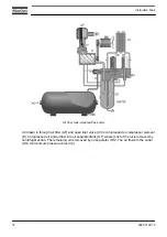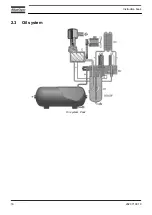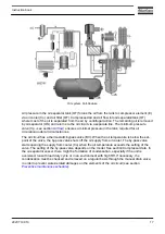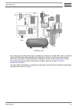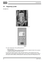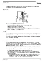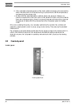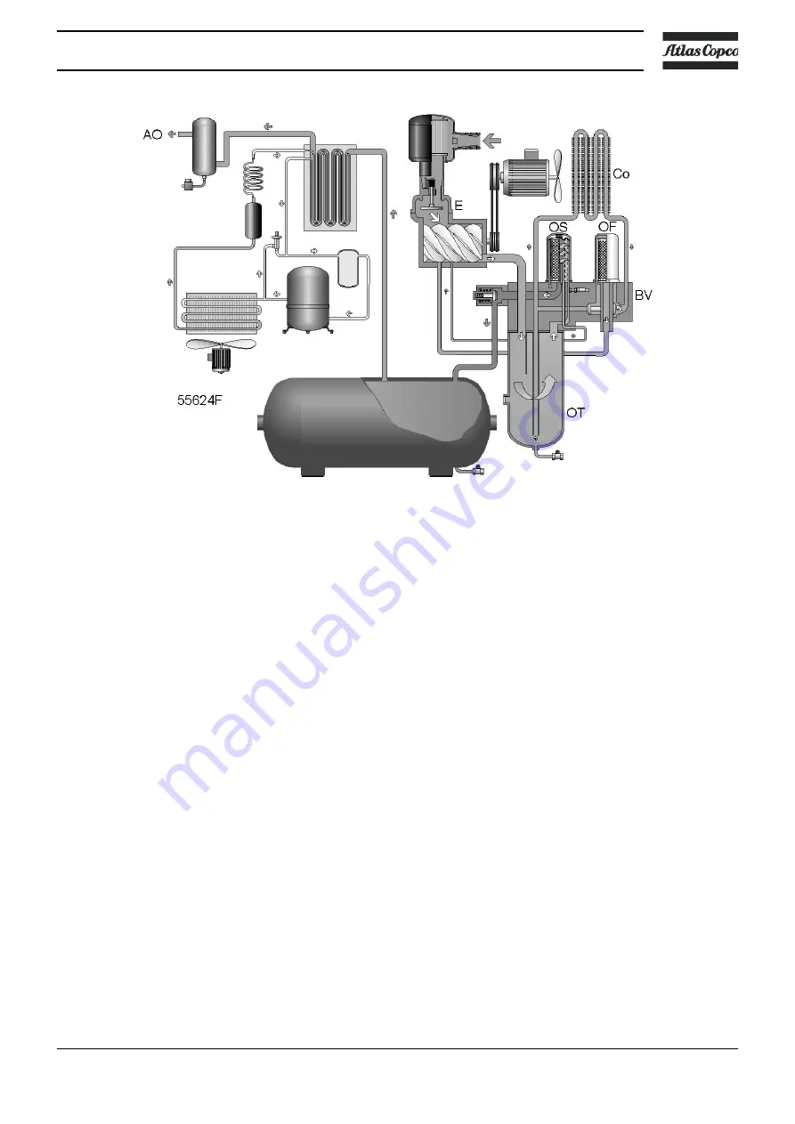
Oil system, Full-Feature
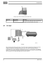
Air pressure in the oil separator tank (OT) forces the oil from the tank to compressor element (E)
via oil cooler (Co) and oil filter (OF). Compressed air and oil flow into oil separator/tank (OT)
where most of the oil is separated from the air by centrifugal action. The remaining oil is removed
by oil separator (OS) and returns to the oil circuit via a separate line. The minimum pressure
valve (Vp - see section
) ensures a minimal pressure in the tank, required for oil
circulation under all circumstances.
The oil circuit has a thermostatic bypass valve (BV). When the oil temperature is below the set-
point of the valve, the by-pass valve shuts off the oil supply from oil cooler. The by-pass valve
starts opening the supply from cooler (Co) when the oil temperature exceeds the setting of the
valve. The setting of the by-pass valve depends on the model. See section Compressor data. In
the oil separator vessel, there might be formation of condensation, especially if the unit is
oversized, run with load duty cycle or in an environment with high RH. If necessary, the
condensation must be checked and removed on a regular basis through the manual drain valve,
in order to prevent water-related damages on the elements of the oil circuit (see section
Preventive maintenance schedule
).
Instruction book
2920 7199 10
17
Summary of Contents for G 2
Page 1: ...INSTRUCTION BOOK OIL INJECTED ROTARY SCREW COMPRESSORS G 2 G 3 G 4 G 5 G 7 ...
Page 2: ......
Page 15: ...2 2 Air flow Pack Air flow floor mounted Pack units Instruction book 2920 7199 10 13 ...
Page 18: ...2 3 Oil system Oil system Pack Instruction book 16 2920 7199 10 ...
Page 20: ...2 4 Cooling system Pack units Instruction book 18 2920 7199 10 ...
Page 60: ...Start up Start up sheet Label on the top Instruction book 58 2920 7199 10 ...
Page 92: ......
Page 93: ......

