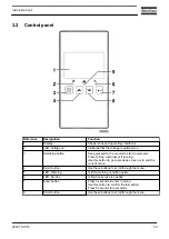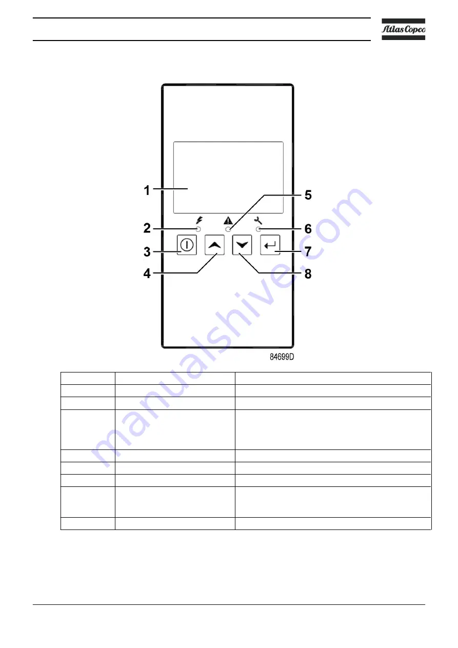
3.2
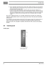
Control panel
Reference
Designation
Function
1
Display
Shows icons and operating conditions.
2
LED, Voltage on
Indicates that the voltage is switched on.
3
Start/stop button
Keep pressed for 3 seconds to start compressor.
Press to stop compressor if running.
Use this button to go to previous screen or to end the
current action.
4
Scroll button
Use these buttons to scroll through the menu.
5
LED, Warning
Is lit if a warning condition exists.
6
LED, Service
Is lit when service is needed.
7
Enter button
Press 3 seconds to enter in menu.
Use this button to confirm the last action.
Press 5 seconds to reset alarm.
8
Scroll button
Use these buttons to scroll through the menu.
Instruction book
2920 7199 10
29
Summary of Contents for G 2
Page 1: ...INSTRUCTION BOOK OIL INJECTED ROTARY SCREW COMPRESSORS G 2 G 3 G 4 G 5 G 7 ...
Page 2: ......
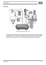
Page 15: ...2 2 Air flow Pack Air flow floor mounted Pack units Instruction book 2920 7199 10 13 ...
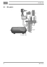
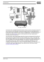
Page 18: ...2 3 Oil system Oil system Pack Instruction book 16 2920 7199 10 ...
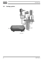
Page 20: ...2 4 Cooling system Pack units Instruction book 18 2920 7199 10 ...
Page 60: ...Start up Start up sheet Label on the top Instruction book 58 2920 7199 10 ...
Page 92: ......
Page 93: ......

