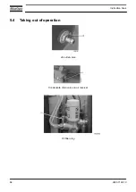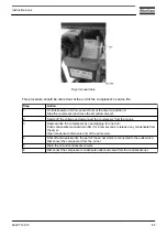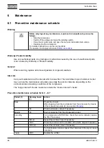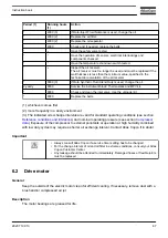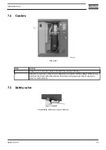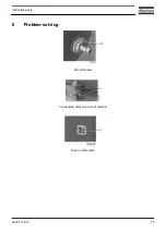
Procedure
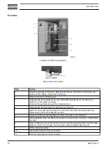
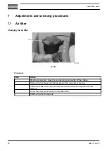
Location of oil filter and separator
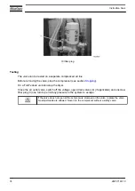
Drain valve of air receiver
Step
Action
1
Run the compressor until warm. Stop the compressor, close the air outlet valve and
switch off the voltage. (See section
2
Remove the front and top panels.
3
Depressurize the compressor by unscrewing filler plug (8) one turn to permit any
pressure in the system to escape.
Remove the plug after the system is depressurized.
4
Depressurize the air receiver by opening drain valve (4).
5
Drain the oil by opening drain valve (5). Close the valve after draining. Deliver the
drained oil to the local oil collection service.
6
Remove oil filter (3) and separator (2). Clean the seats on the manifold.
7
Oil the gaskets of the new filter and separator and screw them into place. Tighten firmly
by hand.
8
Remove filler plug (8) and fill oil tank (7) with oil until the level reaches the top of sight-
glass (6). Ensure no dirt gets into the system. Refit and tighten filler plug (8).
9
Fit the bodywork panels.
10
Close drain valve (4) of the air receiver.
11
Run the compressor for a few minutes.
Instruction book
70
2920 7199 10
Summary of Contents for G 2
Page 1: ...INSTRUCTION BOOK OIL INJECTED ROTARY SCREW COMPRESSORS G 2 G 3 G 4 G 5 G 7 ...
Page 2: ......
Page 15: ...2 2 Air flow Pack Air flow floor mounted Pack units Instruction book 2920 7199 10 13 ...
Page 18: ...2 3 Oil system Oil system Pack Instruction book 16 2920 7199 10 ...
Page 20: ...2 4 Cooling system Pack units Instruction book 18 2920 7199 10 ...
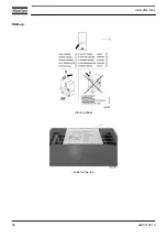
Page 60: ...Start up Start up sheet Label on the top Instruction book 58 2920 7199 10 ...
Page 92: ......
Page 93: ......

