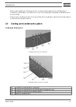
A condensate trap is installed downstream of the air cooler to prevent condensate from entering the air outlet
pipe. The trap is provided with a float valve for automatically draining condensate and with a manual drain
valve.
On Full-Feature compressors a condensate trap is also installed downstream of the dryer. This trap is also
provided with a float valve for automatically draining condensate.
Cooling system
On air-cooled compressors, the air and oil coolers are cooled by fans.
Water-cooled compressors are provided with a cooling water system, including combined oil and air coolers.
2.4
Energy recovery system
General description
The maximum allowed pressure at the water side of the heat exchanger is 10 bar (145 psi).
The energy required in any compression process is mainly transformed into heat. The major part of the
compression heat is dissipated through the oil system. The Atlas Copco energy recovery systems are designed
to recover most of the above-mentioned heat as warm or hot water without any adverse influence on the
compressor performance.
After the compression stage, the oil is separated from the compressed air. The compressed air flows to the
aftercooler and the oil flows to the oil cooler. The energy in the oil can be recovered by installing a heat
exchanger in front of the oil cooler.
The energy recovery systems can be applied as low temperature rise / high water flow systems (e.g. central
heating in closed water circuits) or as high temperature rise / low water flow systems (e.g. pre-heating of
boiler feed water in open water circuits).
Main components
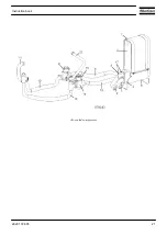
The system mainly comprises:
• Oil/water heat exchanger (HE)
• Energy recovery valve (Y152)
• Oil by-pass valve (Y151)
• Temperature sensors for water inlet and outlet
• The necessary pipes, brackets, bolts, etc.
Installation
The package includes:
• a general by-pass system, to shut down the energy recovery system
• a by-pass system to prevent the oil outlet temperature from dropping below the minimum value.
When the Energy Recovery system is working, this by-pass system makes the oil flow through the Energy
Recovery heat exchanger instead of the normal oil cooler
Instruction book
18
2920 1728 05
Summary of Contents for GA 110 VSD
Page 1: ...GA 110 VSD GA 132 VSD GA 160 VSD Instruction book ...
Page 2: ......
Page 17: ...Rear view of air cooled GA Instruction book 2920 1728 05 15 ...
Page 23: ...Air cooled compressors Instruction book 2920 1728 05 21 ...
Page 30: ...Instruction book 28 2920 1728 05 ...
Page 31: ...Instruction book 2920 1728 05 29 ...
Page 32: ...Instruction book 30 2920 1728 05 ...
Page 33: ...Instruction book 2920 1728 05 31 ...
Page 34: ...Instruction book 32 2920 1728 05 ...
Page 35: ...Instruction book 2920 1728 05 33 ...
Page 36: ...Instruction book 34 2920 1728 05 ...
Page 79: ...Dimension drawing of air cooled Full Feature VSD compressors Instruction book 2920 1728 05 77 ...
Page 100: ...Instruction book 98 2920 1728 05 ...
Page 101: ...Instruction book 2920 1728 05 99 ...
Page 103: ...Figure A Instruction book 2920 1728 05 101 ...
Page 104: ...Figure B Instruction book 102 2920 1728 05 ...
Page 107: ...Text on figure Instruction book 2920 1728 05 105 ...
Page 164: ......
Page 165: ......


