background image

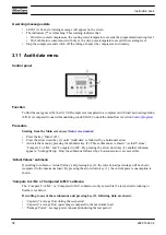
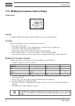
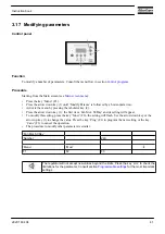
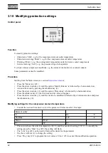
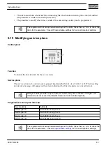
3.13 Counters menu

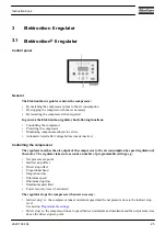
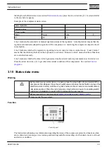
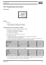
Control panel

Function

To call up:

• The loaded hours
• The number of motor starts
• The number of hours the regulator (module) has been under tension
• The accumulated volume

Procedure

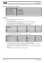
Starting from the Main screen (see section 

Main screen menu

):

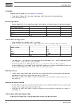
• Press the key ‘Menu’ (F1).
• Press the arrow down key (1) until ‘Counters’ is followed by a horizontal arrow.
• Press the tabulator key (2) to activate the menu.
• By pressing the arrow key (1), the above-mentioned data can be found.

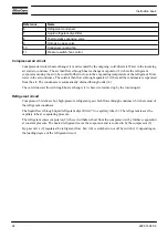
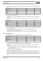
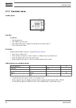
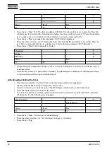
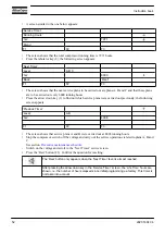
Calling up the accumulated volume

‘Accumulated vol’
‘1000 m3’

230

.
‘Menu’

‘Mod.’

F1

F2

F3

• Consult the procedure above to select ‘Accumulated vol’.
• In the example above, the display indicates that the compressor has delivered 230 x 1000 m

3

If it should be required to modify the value of the indicated timer, consult Atlas Copco.

Instruction book

38

2920 1634 04

Summary of Contents for GA 75 VSD

Page 1: ...GA 75 VSD GA 90 VSD Instruction book ...

Page 2: ......

Page 3: ... part thereof is prohibited This applies in particular to trademarks model denominations part numbers and drawings This instruction book meets the requirements for instructions specified by the machinery directive 98 37 EC and is valid for CE as well as non CE labelled machines 2008 01 No 2920 1634 04 www atlascopco com ...

Page 4: ... 17 2 4 COOLING SYSTEM 18 2 5 CONDENSATE SYSTEM 19 2 6 REGULATING SYSTEM 19 2 7 ELECTRICAL SYSTEM 20 2 8 ELECTRICAL DIAGRAMS 21 2 9 AIR DRYER 23 3 Elektronikon II regulator 25 3 1 ELEKTRONIKON II REGULATOR 25 3 2 CONTROL PANEL 27 3 3 FUNCTION KEYS 28 3 4 SCROLL KEYS 29 3 5 EMERGENCY STOP BUTTON 29 3 6 CONTROL PROGRAMS 30 3 7 MAIN SCREEN MENU 31 3 8 CALLING UP MENUS 32 3 9 QUICK LOOK AT THE ACTUAL ...

Page 5: ... CONFIGURATION SETTINGS 49 3 22 PROGRAMMING COMPRESSOR CONTROL MODES 50 3 23 SERVICE MENU 51 3 24 SAVED DATA MENU 53 3 25 PROGRAMMABLE SETTINGS 53 4 OSD oil condensate separator optional 57 4 1 OSD UNIT 57 4 2 INSTRUCTIONS FOR FIELD INSTALLATION 58 4 3 OPERATING AND MAINTENANCE INSTRUCTIONS 59 4 4 PICTOGRAPHS 61 5 Energy recovery optional 62 5 1 ENERGY RECOVERY UNIT 62 5 2 ENERGY RECOVERY SYSTEMS ...

Page 6: ... DURING OPERATION 84 7 6 CHECKING THE DISPLAY 86 7 7 STOPPING 87 7 8 TAKING OUT OF OPERATION 87 8 Maintenance 89 8 1 PREVENTIVE MAINTENANCE SCHEDULE 89 8 2 DRIVE MOTOR 91 8 3 OIL SPECIFICATIONS 92 8 4 OIL AND OIL FILTER CHANGE 92 8 5 DISPOSAL OF USED MATERIAL 94 8 6 STORAGE AFTER INSTALLATION 94 8 7 SERVICE KITS 94 9 Adjustments and servicing procedures 96 9 1 AIR FILTER 96 9 2 COOLERS 96 9 3 SAFE...

Page 7: ... MOTOR CIRCUIT BREAKER 103 11 4 REFERENCE CONDITIONS AND LIMITATIONS 103 11 5 COMPRESSOR DATA 104 12 Instructions for use of air receiver 108 12 1 AIR RECEIVER INSTRUCTIONS 108 13 Guidelines for inspection 109 13 1 GUIDELINES FOR INSPECTION 109 14 PED 110 14 1 PRESSURE EQUIPMENT DIRECTIVES 110 Instruction book 2920 1634 04 5 ...

Page 8: ...ment or any other non routine checks stop the compressor press the emergency stop button switch off the voltage and depressurise the compressor In addition the power isolating switch must be opened and locked 6 Never play with compressed air Do not apply the air to your skin or direct an air stream at people Never use the air to clean dirt from your clothes When using the air to clean equipment do...

Page 9: ... or if the automatic restart function after voltage failure is activated a sign stating This machine may start without warning must be affixed near the instrument panel 13 In multiple compressor systems manual valves must be installed to isolate each compressor Non return valves check valves must not be relied upon for isolating pressure systems 14 Never remove or tamper with the safety devices gu...

Page 10: ...precautions to ensure that there is no one checking or working on the machine To this end a suitable notice shall be affixed to the remote start equipment 3 Never operate the machine when there is a possibility of taking in flammable or toxic fumes vapours or particles 4 Never operate the machine below or in excess of its limit ratings 5 Keep all bodywork doors shut during operation The doors may ...

Page 11: ...nt or any other non routine checks stop the compressor press the emergency stop button switch off the voltage and depressurise the compressor In addition the power isolating switch must be opened and locked 6 Never play with compressed air Do not apply the air to your skin or direct an air stream at people Never use the air to clean dirt from your clothes When using the air to clean equipment do s...

Page 12: ...tect the motor air filter electrical and regulating components etc to prevent moisture from entering them e g when steam cleaning 19 Make sure that all sound damping material e g on the bodywork and in the air inlet and outlet systems of the compressor is in good condition If damaged replace it by genuine material from the manufacturer to prevent the sound pressure level from increasing 20 Never u...

Page 13: ...sors driven by an electric motor GA Workplace GA Workplace are enclosed in a sound insulated bodywork The compressors are controlled by the Atlas Copco Elektronikon II regulator The electronic control module is fitted to the door at the right side An electric cabinet comprising fuses transformers relays etc is located behind this panel An automatic condensate drain system is provided Front view GA...

Page 14: ...ektronikon II regulator FN Cooling fan MT Condensate trap M1 Drive motor OF Oil filter S3 Emergency stop button VP Vent plug 1 Electric cabinet GA Workplace Full Feature GA Workplace Full Feature FF are enclosed in a sound insulated bodywork The compressors are controlled by the Atlas Copco Elektronikon II regulator The electronic control module is fitted to the door at the right Instruction book ...

Page 15: ...nsate drain system is provided The compressors are provided with an air dryer which is integrated in the sound insulated bodywork The dryer removes condensate from the compressed air by cooling the air to near freezing point Front view GA 75 VSD and GA 90 VSD Workplace Full Feature Instruction book 2920 1634 04 13 ...

Page 16: ...oler Co Oil cooler CV Vs Check valve oil stop valve Da Automatic condensate outlet Da1 Automatic condensate outlet dryer DR Dryer E Compressor element ER Elektronikon II regulator FN Cooling fan MT Condensate trap M1 Drive motor OF Oil filter S3 Emergency stop button VP Vent plug 1 Electric cubicle Instruction book 14 2920 1634 04 ...

Page 17: ...ers on water cooled compressors Water cooled air cooler and oil cooler Reference Name Ca Air cooler Co Oil cooler 2 2 Air flow Flow diagram GA 75 VSD and GA 90 VSD Workplace Instruction book 2920 1634 04 15 ...

Page 18: ...ompressor element E is compressed Compressed air and oil flow into the air receiver oil separator AR The air is discharged through the outlet valve via minimum pressure valve Vp air cooler Ca and condensate trap MT Minimum pressure valve Vp prevents the receiver pressure from dropping below a minimum pressure and includes a check valve which prevents blow back of compressed air from the net Full F...

Page 19: ...e oil collects in the lower part of air receiver oil separator AR which serves as oil tank The oil system is provided with a by pass valve BV When the oil temperature is below 60 C 140 F by pass valve BV shuts off the oil supply from oil cooler Co Air pressure forces the oil from air receiver AR through oil filter OF and oil stop valve Vs to compressor element E and the lubrication points Oil cool...

Page 20: ... case of a Full Feature unit to the dryer Note The cooling fan is not provided on water cooled compressors Description The cooling system comprises air cooler Ca and oil cooler Co Air cooled compressors have a cooling fan FN Water cooled compressors have a cooling water system The water flows through the inlet pipe the coolers and the outlet pipe Instruction book 18 2920 1634 04 ...
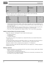
Page 21: ...r is collected by water drain EWD1 and discharged through drain outlet Da1 Also see section Air flow Testing the electronic water drain can be done by pressing the test button 1 on top of the drain 2 6 Regulating system Description If the consumption is less than the air output of the compressor the net pressure increases When the net pressure is higher than the set point desired net pressure the ...

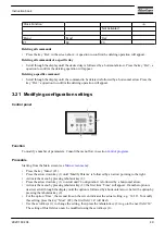
Page 22: ...The electrical system comprises the frequency converter and following components Electric cabinet for GA 75 VSD and GA 90 VSD typical example References Reference Designation F1 2 Fuses F4 5 6 Fuses K21 Delta contactor L1 L2 L3 Terminals power supply Q15 Circuit breaker T1 Transformer Instruction book 20 2920 1634 04 ...
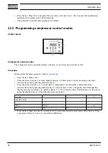
Page 23: ...p 2 Remote start stop 3 Overload fan motor 4 Fault EWD 5 Dp of DD filter 6 Dp of PD filter 7 Remote pressure set selection 8 Overload fan motor IT version 9 Remote emergency stop 10 Auxiliary contacts 11 Manual operation 12 Automatic operation 13 General warning 14 General shut down Instruction book 2920 1634 04 21 ...
Page 24: ...ull Feature Y1 Loading solenoid valve Reference Starter cubicle F1 F12 Fuses K11 Auxiliary contactor for dryer Full Feature K15 Contactor fan motor K21 Main contactor L1 Filter Q15 Circuit breaker fan motor SS Service switch T1 Transformer U1 Frequency converter Z1 E M C filter 1X1 1X7 Terminal strips X101 X121 Connectors Reference Control module I Start button K01 Auxiliary relay fan motor K02 Au...

Page 25: ...switch TSLL91 Thermostat cubicle freeze protection TSLL92 Thermostat converter freeze protection TT91 Temperature sensor cubicle freeze protection TT92 Temperature sensor converter freeze protection Y51 Water shut off valve water cooled compressors 2 9 Air dryer Flow diagram Air dryer Reference Name AI Air inlet AO Air outlet 1 Air air heat exchanger 2 Air refrigerant heat exchanger evaporator 3 C...

Page 26: ...the air The condensate is automatically drained through outlet 4 The cold dried air flows through heat exchanger 1 where it is warmed up by the incoming air Refrigerant circuit Compressor 5 delivers hot high pressure refrigerant gas which flows through condenser 6 where most of the refrigerant condenses The liquid flows through liquid refrigerant dryer filter 7 to capillary tube 8 The refrigerant ...

Page 27: ...gulator matches the air output of the compressor to the air consumption by speed regulation of the motor The regulator takes into account a number of programmable settings e g Net pressure set point Indirect stop offset Direct stop offset Proportional band Integration time Minimum speed Minimum stop time Maximum speed limit Power recovery time if activated The regulator stops the compressor whenev...

Page 28: ...ervice plan has a programmed time interval If a time interval is exceeded a message will appear on display 1 to warn the operator to carry out the service actions belonging to that plan Warning A warning message also appears if On water cooled compressors the cooling water outlet temperature exceeds the warning level On Full Feature compressors the dewpoint temperature exceeds the warning level Au...

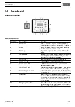
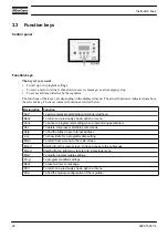
Page 29: ... Voltage on LED Indicates that the voltage is switched on 7 General alarm LED Is lit if a warning service warning or shut down warning condition exists 7 General alarm LED Flashes if a shut down condition exists if an important sensor is out of order or after an emergency stop 8 Automatic operation LED Indicates that the regulator is automatically controlling the compressor 9 Stop button Button to...

Page 30: ...ack To return to a previously shown option or menu Canc To cancel a programmed setting when programming parameters Del To delete compressor start stop commands Help To find the Atlas Copco Internet address Lim To show limits for a programmable setting Main To return from a menu to the main screen Menu Starting from the main screen to have access to the submenus Menu Starting from a submenu to retu...

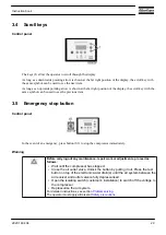
Page 31: ...n emergency press button S3 to stop the compressor immediately Warning Before carrying out any maintenance repair work or adjustments proceed as follows Wait until the compressor has stopped Close the air outlet valve Unlock the button by pulling it out Press the test button on top of the electronic water drain s until the air system between the air receiver and outlet valve is fully depressurised...

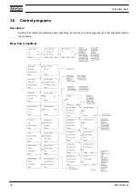
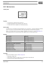
Page 32: ...6 Control programs Description In order to facilitate programming and controlling menu driven control programs have been implemented in the regulator Menu flow simplified Instruction book 30 2920 1634 04 ...
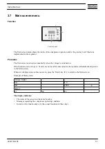
Page 33: ... keys 1 2 and 3 are not used for some minutes the regulator will automatically return to the Main screen Whenever displayed on a submenu screen press the Main key F1 to return to the Main screen Example of Main screen Compr Outlet bar 7 0 rpm 2500 Menu F1 F2 F3 The display indicates The name of the sensor and its actual reading Messages regarding the compressor operating condition Just above the f...

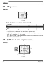
Page 34: ...e actual compressor status After pressing the Menu F1 key the option Status data will be followed by a horizontal arrow Either press the tabulator key 2 to select this menu Or use the arrow down key 1 until the desired submenu is followed by a horizontal arrow and then press the tabulator key 2 to select this menu 3 9 Quick look at the actual compressor status Procedure Control panel Instruction b...

Page 35: ...ommands is activated or not Press the arrow down key 3 to get other data actual condition of the compressor See section Control programs 3 10 Status data menu Warning Before starting any maintenance or repairs press the stop button 4 and wait until the compressor has stopped Close the air outlet valve and press the test button on top of the electronic water drain s until the air system between the...

Page 36: ...nus e g to check the values of other parameters When returning to the Status data menu the option Shutdowns will flash This option can be selected by pressing the tabulator key 2 to return to the above shut down screen Shut down reset Switch off the voltage and remedy the trouble After remedying and when the shut down condition has disappeared switch on the voltage and press the key Rset F3 Press ...

Page 37: ...lit The Main screen will change into a screen similar to the one below Compr Outlet bar 7 0 Serv Requir Menu F1 F2 F3 The indicators are flashing and the service warning message appears Press the key Menu F1 and the tabulator key 2 to select the Status data menu the option Service is flashing Scroll to this option and select it by pressing the tabulator key 2 following options may flash Inputs if ...

Page 38: ...til Audit data is followed by a horizontal arrow Activate the menu by pressing the tabulator key 2 Three submenus are shown Actual Values Compare To L NL and Compared to MC By pressing the arrow down key 1 another submenu appears Settings Setup Only the submenus followed by a horizontal arrow are accessible Actual Values submenu If scrolling to submenu Actual Values and pressing key 2 the current ...

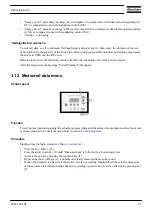
Page 39: ... time of the period in hours After the test period the message Period Finished will appear 3 12 Measured data menu Control panel Function To call up information regarding the actually measured data and the status of some inputs such as the motor overload protection Consult the menu flow in section Control programs Procedure Starting from the Main screen see Main screen menu Press the key Menu F1 P...

Page 40: ...til Counters is followed by a horizontal arrow Press the tabulator key 2 to activate the menu By pressing the arrow key 1 the above mentioned data can be found Calling up the accumulated volume Accumulated vol 1000 m3 230 Menu Mod F1 F2 F3 Consult the procedure above to select Accumulated vol In the example above the display indicates that the compressor has delivered 230 x 1000 m3 If it should be...

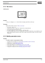
Page 41: ...will generate a series of patterns on the display which enable the operator to check that each pixel still functions normally at the same time the LEDs are lit 3 15 Modify parameters menu Function To modify a number of programmable settings Compressor motor settings see section Modifying compressor and motor settings Parameters see section Modifying parameters Protections see section Modifying pro...

Page 42: ...w Modifying the net pressure set points If desired the operator can program two set points Setpoint 1 and Setpoint 2 Consult the steps above to select Setpoint 1 Setpoint 1 bar 7 0 Menu Mod F1 F2 F3 The screen shows that the current setting is 7 0 bar e To modify this setting press the key Mod F2 the setting will flash The key Lim F2 can be used to find out the limitations for the parameter Use th...

Page 43: ...m Fan Mot St Day and its setting will appear To modify this setting press the key Mod F2 the setting will flash Use the arrow down key or the arrow up key 1 to change the value Press the key Prog F1 to program the new setting or the key Canc F3 to cancel the operation The procedure to modify other parameters is similar Fan Mot St Day Number 240 Menu Mod F1 F2 F3 The regulator will not accept new v...

Page 44: ... the menu by pressing the tabulator key 2 Press the arrow down key 1 until the option Protections is followed by a horizontal arrow Press the tabulator key 2 the first item and its value will appear Press the arrow down key 1 until the item to be modified is followed by a horizontal arrow and press the tabulator key 2 Modifying settings for the compressor element temperature Consult the section Pr...

Page 45: ...e carried out are grouped in plans called Service level A B C or D When reaching an interval a message will appear on the screen indicating which Service plans are to be carried out Always consult your Atlas Copco Customer Centre if any timer should be changed The intervals must not exceed the intervals below and must coincide logically Programmed service plan intervals Service plans Intervals Ser...

Page 46: ...llowed by a horizontal arrow Press the tabulator key 2 a screen similar to the one below will appear Service Timer Running hours hrs 2130 Menu F1 F2 F3 The screen shows the actual running hours Press the tabulator key 2 a screen similar to the one below will appear Service Timer Level A hrs 4000 Menu Mod F1 F2 F3 The screen indicates that the level for Service plan A is set at 4000 running hours P...

Page 47: ...Menu F1 Press the arrow down key 1 until Modify Params is followed by a horizontal arrow Activate the menu by pressing tabulator key 2 Use the arrow down key 1 to scroll until the option Clock Function is followed by a horizontal arrow Activate the menu by pressing tabulator key 2 the following screen appears Clock Function Not Activated Menu Mod Del F1 F2 F3 Press the tabulator key 2 the followin...

Page 48: ...over at 18 o clock to setpoint 2 is carried out in a similar way as described above Press the key Menu F1 and scroll to Saturday Programming the command 18 00 Compressor Stop is carried out in a similar way as described above Activating deactivating the timer The timer can only be activated if at least one start stop command is programmed Starting from the Main screen press the key Menu F1 Use arr...

Page 49: ...tion Not Activated Menu Mod Del F1 F2 F3 Press the tabulator key 2 the following screen appears Monday Tuesday Wednesday Menu Del F1 F2 F3 Scroll through the display until Saturday is followed by a horizontal arrow Press the tabulator key 2 If necessary scroll through the commands until the command to be modified is followed by a horizontal arrow Press the key Mod the first two digits of the comma...

Page 50: ...etpoint 2 must be added to the following list 06 00 Start Compressor 06 00 Setpoint 1 18 00 Stop Compressor The regulator does not allow the entering of a new command which time wise is situated before the last command in the list Scroll through the display until the command before which the new command must be entered is followed by a horizontal arrow in the example above 18 00 Stop Compressor an...

Page 51: ...cedure Starting from the Main screen see Main screen menu Press the key Menu F1 Press the arrow down key 1 until Modify Params is followed by an arrow pointing to the right Activate the menu by pressing tabulator key 2 Press the arrow down key 1 to scroll until Configuration is followed by a horizontal arrow Activate the menu by pressing tabulator key 2 the first item Time will appear If another o...

Page 52: ...odify Params is followed by an arrow pointing to the right Activate the menu by pressing tabulator key 2 Press the arrow down key 1 to scroll until Configuration is followed by a horizontal arrow Activate the menu by pressing tabulator key 2 the first item Time will appear Scroll through the display using the scroll keys 1 until the option C C M is followed by a horizontal arrow and select it usin...

Page 53: ...ervice actions related to the indicated levels the timers must be reset Example Service plans Intervals Service plan A Every 4000 running hours Service plan B Every 4000 running hours Service plan C Every 8000 running hours Service plan D Every 24000 running hours Resulting service actions according to At Service plan A and B 4000 running hours Service plan A B and C 8000 running hours Service pla...

Page 54: ... screen appears Previous Timer Level A B hrs 4008 F1 F2 F3 The screen shows that service plans A and B were carried out at 4008 running hours Stop the compressor switch off the voltage and carry out the service operations related to plans A B and C See section Preventive maintenance schedule Switch on the voltage and scroll to the Next Timer service screen Press the Rset button F3 Confirm the ques...

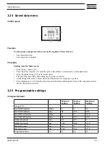
Page 55: ...he items to select the desired shut down or emergency stop item Press tabulator key 2 to find the date time and other data reflecting the status of the compressor when the last shut down occurred 3 25 Programmable settings Compressor motor Minimum setting Factory setting Maximum setting Set point 1 2 GA VSD Workplace bar e 4 7 13 GA VSD Workplace psig 58 100 188 GA VSD Full Feature bar e 4 7 12 8 ...

Page 56: ...meters Minimum setting Factory setting Maximum setting Minimum stop time GA 75 VSD sec 5 5 30 GA 90 VSD sec 5 5 30 Power recovery time sec 10 10 3600 Restart delay sec 0 0 1200 Communication time out sec 10 30 60 On air cooled compressors also Fan motor starts per day 1 240 240 Protections Minimum setting Factory setting Maximum setting Compressor element outlet temperature shut down warning level...

Page 57: ...tlet temperature warning level C 0 60 99 Cooling water outlet temperature warning level F 32 140 210 Delay at warning signal sec 0 0 255 Delay at start sec 0 0 255 Service plan Also see section Preventive maintenance schedule Consult Atlas Copco in case any timer setting should be changed The intervals must not exceed the nominal intervals and must coincide logically See section Modifying service ...

Page 58: ...e generating a warning The setting should be less than the setting for the delay at signal Minimum stop time Once the compressor has automatically stopped it will remain stopped for the minimum stop time approx 20 seconds whatever happens with the net air pressure Consult Atlas Copco if a setting lower than 20 seconds should be required Oil separator Use Atlas Copco oil separators The recommended ...

Page 59: ...igned to separate the major part of this oil from the condensate and to catch the oil in a collector The condensate meets the requirements of the environmental codes General view of OSD 90 typical example Reference Designation 1 Vessel 2 Pressure gauge filter 3 Oil filter 4 Oil collector 5 Condensate inlet 6 Dp of filter 7 Clean condensate outlet 8 Oil outlet 9 Cover 10 Pre filter Instruction book...

Page 60: ...led to water vessel 1 where the oil rises due to the difference in specific mass The vessel is provided with two separated outlets one for condensate 7 which is led outside the bodywork and one for the separated oil 8 which is caught in collector 4 4 2 Instructions for Field installation Location of OSD GA 55 up to GA 90 GA 75 VSD and GA 90 VSD Condensate drains GA Workplace Instruction book 58 29...

Page 61: ...move the coupling Da and install the couplings delivered with the separator kit Connect water tube 5 to the rear side of coupling Dc Lead the condensate outlet flexible from coupling Dc towards the condensate drain system For Workplace Full Feature compressors repeat this action by removing coupling Da1 and install and connect coupling Dc1 from the second OSD 7 Remove the cover 6 and fill vessel 7...

Page 62: ...pressor and its operation cycle the humidity of the inlet air and the oil content of the compressed air it may take several weeks or months before an oil level is observed in collector 4 Regularly check that vessel 1 is filled If necessary gently pour water into filler pipe 2 until it flows through tube 3 Keep the cover installed Condensate drains GA and GA VSD Workplace GA Full Feature and GA VSD...

Page 63: ... Check the oil level in collector 4 If nearly full disconnect oil tube 8 and deliver the oil to the local oil collection service Reinstall an empty collector Check pre filter 10 clean it if necessary 4 4 Pictographs Pictographs shown on OSD Reference Description 1 Oil 2 Oil outlet 3 Condensate outlet 4 Pressure 5 Inlet 6 Service point drain 7 Separator inlet pressure 8 Oil gasket screw on filter a...

Page 64: ...compressor performance The water can be used for diverse applications Components The energy recovery system is completely integrated and mainly comprises Stainless steel oil water heat exchanger Selector handle V1 to enable disable Energy Recovery Thermostatic by pass valve for energy recovery heat exchanger s BV2 Two temperature sensors for water inlet and outlet control 3 and 4 The necessary bol...

Page 65: ...ater flow is needed for maximum energy recovery Example The heated water is used to keep another medium at a moderately high temperature in a closed circuit e g central heating High temperature rise low water flow open water recovery systems For this type of application a high water temperature rise in the energy recovery system is obtained which consequently brings on a low flow rate Example An o...

Page 66: ...rgy recovery Bypass valve BV2 is integrated in the ER unit and controls the working of the oil water heat exchanger HE of the ER unit Bypass valve BV1 is integrated in the oil filter housing of the compressor and controls the working of the main oil cooler Co of the compressor Both bypass valves consist of an insert thermostat mounted in a housing Bypass valve BV2 has a separate housing while BV1 ...

Page 67: ...BV2 that starts opening at 60 C 140 F and which is completely open at 75 C 167 F The housing of BV2 is provided with a special handle V1 allowing to control the working of the energy recovery system As can be seen on the ER label the ER unit is integrated in the oil circuit and will recover energy when the handle is completely turned in clockwise When the handle is turned out anticlockwise the hea...

Page 68: ...lowing the oil to flow through the heat exchanger HE As the oil temperature rises to approx 15 C 27 F above the set point all the oil passes through the heat exchanger The exchange of heat between the compressor oil and the heat recovery water is maximum The oil from the heat exchanger outlet flows via oil filter OF oil stop valve Vs if present compressor element E and separator AR back to the inl...

Page 69: ...r draining Thermostatic bypass valves The inserts thermostats must be replaced by new ones when abnormal function is noticed Examples regulating temperature is not within the normal range ER heat exchanger remains cold Heat exchanger HE If the temperature rise over the energy recovery system declines over a period of time with the same basic working conditions the heat exchanger should be inspecte...

Page 70: ...C 0 Depends on application 99 Energy recovery water outlet F 32 Depends on application 210 Delay at signal sec 0 Consult Atlas Copco 255 Delay at start sec 0 Consult Atlas Copco 255 To modify a setting consult section Modifying parameters Recoverable energy The recoverable energy can be calculated by using the following formula RECOVERED ENERGY kW 4 2 x water flow l s x water temperature rise C In...

Page 71: ...5 VSD GA90 VSD Recoverable energy kW 56 3 67 5 Recoverable energy hp 75 5 90 5 Water flow l min 11 3 13 6 Water flow cfm 0 40 0 48 Temperature at inlet C 20 20 Temperature at inlet F 68 68 Temperature at outlet C 91 91 Temperature at outlet F 196 196 Instruction book 2920 1634 04 69 ...
Page 72: ...6 Installation 6 1 Dimension drawings GA 75 VSD and GA 90 VSD GA 75 VSD and GA 90 VSD Instruction book 70 2920 1634 04 ...
Page 73: ...30 1680 GA 75 VSD lb 4035 3704 GA 90 VSD kg 1880 1730 GA 90 VSD lb 4145 3815 Weights in kg oil included 50 kg 110 lb Reference Designation 1 Electric cable passage 2 Cooling water outlet 3 Cooling water inlet 4 Compressor cooling air outlet 5 Dryer cooling air outlet 6 Compressed air outlet 7 Cooling air inlet 8 Energy recovery outlet 9 Energy recovery inlet 10 Compressed air dryer bypass outlet 1...

Page 74: ...6 2 Installation proposal Compressor room example Compressor room example Text on drawing Instruction book 72 2920 1634 04 ...

Page 75: ... input of compressor in kW dT Temperature increase in compressor room For alternatives 2 and 4 the fan capacity should match the compressor fan capacity at a pressure head equal to the pressure drop over the air ducts For GA 37 VSD up to GA 90 VSD water cooled compressors the ventilation capacity required to limit the compressor room temperature can be calculated as follows Qv 0 13 N dT for GA VSD...

Page 76: ...e according to the maximum cooling water inlet pressure see section Reference conditions and limitations has to be installed between the compressor water outlet pipe and shut off valve When operating the unit the operator must ensure that the cooling water system cannot be blocked The above mentioned applies also to the energy recovery cooling water system Remove the plastic plugs if provided from...

Page 77: ...6 3 Electrical connections Electrical connections for GA 75 VSD and GA 90 VSD Instruction book 2920 1634 04 75 ...

Page 78: ...ide Cl less than 600 mg l less than 150 mg l Sulphate SO4 less than 400 mg l less than 250 mg l Total solids less than 3000 mg l less than 750 mg l Suspended solids as SiO2 less than 10 mg l less than 10 mg l Free chorine Cl2 less than 4 mg l less than 2 mg l Ammonia NH4 less than 0 5 mg l less than 0 5 mg l Copper less than 0 5 mg l less than 0 5 mg l Iron less than 0 2 mg l less than 0 2 mg l Ma...

Page 79: ...ge 5 Automatic condensate drain 6 Stop the compressor before cleaning the coolers 7 Lightly oil the gasket of the oil filter screw it on and tighten by hand approx half a turn 8 Before connecting the compressor electrically consult the Instruction book for the motor rotation direction 9 Compressor remains pressurized for 30 seconds after switching off the voltage 10 Torques for steel Fe or brass C...

Page 80: ...g bolts See section Initial start up Make sure that the forks protrude from the other side of the frame The compressor can also be lifted after inserting beams into the slots Make sure that the beams cannot slide and that they protrude from the frame equally The chains must be held parallel to the bodywork by chain spreaders in order not to damage the compressor The lifting equipment must be place...

Page 81: ...Air receiver transport fixtures of GA 75 VSD and GA 90 VSD Motor and gear casing transport fixtures of GA 75 VSD and GA 90 VSD Instruction book 2920 1634 04 79 ...

Page 82: ...t air outlet valve AV see section Introduction for the position of the valve Close the valve Connect the air net to the valve On compressors equipped with a dryer by pass fit the air outlet valve to the dryer by pass pipe Connect the condensate drain outlet s to a drain collector See section Condensate system and in case of an OSD see section Installation For Full Feature units also connect the co...

Page 83: ...rection of the fan motor Rotation arrows visible through the grating in the roof are provided on the fan plate If the rotation direction is wrong open the isolating switch in the voltage supply line and reverse two incoming electric lines Check the programmed settings Consult section Programmable settings Start and run the compressor for a few minutes Check that the compressor operates normally 7 ...

Page 84: ... plug If necessary empty the dust trap of the filter see section Air filter If the red part of the air filter service indictor shows full out replace the air filter element Reset service indicator VI by pushing the knob in the extremity of the body and reset the service warning see section Service menu On water cooled compressors also Check that the cooling water drain valves in the inlet and outl...

Page 85: ... the compressor running at maximum speed Adjust the water flow to obtain the most suitable air temperature at the element outlet i e between 2 and 7 C 4 and 13 F above the relevant temperature in the figure below For optimum operation the cooling water outlet temperature must never exceed the value specified in section Compressor data Consult Atlas Copco if condensate should be formed during frequ...

Page 86: ...he cooling water flow during loaded operation to obtain a temperature between 70 and approx 75 C 158 and approx 167 F at the outlet of the compressor element 7 5 During operation Procedure The operator must apply all relevant Safety precautions Also consult section Problem solving Keep the doors closed during operation they may be opened for short periods only to carry out checks When the motors a...

Page 87: ...e pointer of level gauge Gl must register in the green range if not press stop button 9 Close air outlet valve AV and press the test button on top of the electronic water drain until the air system between the air receiver and outlet valve is fully depressurised see sections Introduction and Condensate system for their location Instruction book 2920 1634 04 85 ...

Page 88: ...condensate is discharged during operation See section Condensate system and in case of an OSD also check the level in the oil collector see section OSD Maintenance and operating instruction The amount of condensate depends on environmental and working conditions 7 6 Checking the display Procedure Control panel Check the display 2 regularly for readings and messages Normally the display shows the c...

Page 89: ...ssurised See section Condensate system Switch off the voltage On water cooled compressors Close the cooling water inlet valve If freezing temperatures may be expected drain the cooling system completely 7 8 Taking out of operation Warning The operator must apply all relevant Safety precautions Procedure Stop the compressor and close the air outlet valve Press the test button on top of the electron...

Page 90: ...which is connected to the outlet valve Disconnect the compressor air outlet pipe from the air net On water cooled compressors Isolate and disconnect the water system from the cooling water net Drain the water circuit Drain the oil Drain the condensate circuit and disconnect the condensate piping from the condensate net Instruction book 88 2920 1634 04 ...

Page 91: ... compressor For detailed instructions see section Problem solving The operator must apply all relevant Safety precautions Before mechanical maintenance Close the air outlet valve and press the test button on top of the electronic water drain s until the air system between the air receiver and outlet valve is fully depressurised For location of components see section Condensate system Before electr...

Page 92: ...ns are grouped in plans called service plans A B as specified in the schedule below Each plan has a programmed time interval at which all service actions belonging to that plan are to be carried out When reaching the interval a message will appear on the screen indicating which service plans are to be carried out see section Status data menu After servicing the intervals must be reset see section ...

Page 93: ...rictor in scavenging line for cleanness 4000 B Check operation of cooling fans of converter 4000 B Check blow off solenoid valve after stopping and pressing the emergency stop button 8000 C Have oil separator replaced Replace oil separator if the pressure drop exceeds 1 bar during loaded running with a stable working pressure 8000 C If Atlas Copco Roto Xtend Duty Fluid is used change oil and oil f...

Page 94: ...t condition Roto Inject Fluid can be used for compressors operating at ambient temperatures between 0 C 32 F and 40 C 104 F Atlas Copco Roto Xtend Duty Fluid Atlas Copco Roto Xtend Duty Fluid is a high quality synthetic lubricant for oil injected screw compressors which keeps the compressor in excellent condition Roto Xtend Duty Fluid can be used for compressors operating at ambient temperatures b...

Page 95: ...r run for 3 minutes at minimum speed Stop the compressor press the emergency stop button and wait until the compressor has depressurized Unscrew oil filler plug FC only one turn to permit any pressure in the system to escape Loosen the vent plug of the oil cooler and wait for 5 minutes See section Introduction for the position of the vent plug VP Instruction book 2920 1634 04 93 ...

Page 96: ...ssure in the system to escape Remove the plug Fill the air receiver with oil until the level reaches the filler neck Tighten the filler plug Reset the service timer After carrying out all service actions in the relevant Service Plan reset the service warning see section Service menu 8 5 Disposal of used material Used filters or any other used material e g desiccant lubricants cleaning rags machine...

Page 97: ...l range of extensively tested lubricants suitable for your specific needs is available to keep the compressor in excellent condition Consult the Spare Parts List for part numbers Instruction book 2920 1634 04 95 ...

Page 98: ...ove the dust trap and the air filter element Clean the trap Discard the filter element 3 Fit the new element and the trap 4 Reset service indicator 1 by pushing the knob in the extremity of the body 5 Reset the air filter service warning After carrying out all service actions in the relevant Service Plan reset the service warning see section Service menu 9 2 Coolers Cleaning Keep the coolers clean...

Page 99: ...the cover used during cleaning Mount the side baffle that encloses the fan compartment On water cooled compressors Consult Atlas Copco about cleaning 9 3 Safety valve Location of safety valve GA 75 VSD and GA 90 VSD Operating Operate the safety valve by unscrewing the cap one or two turns and retightening it Testing Before removing the valve depressurize the compressor See section Problem solving ...

Page 100: ...ed with the compressor Lift the handle and turn it until the slot of the handle fits over the blocking edge on the valve body Fit the screw The operator must apply all relevant Safety precautions Before mechanical maintenance Press the test button on top of the electronic water drain s until the air system between air receiver and outlet valve is fully depressurized For location of components see ...

Page 101: ...ary On Full Feature compressors dryer piping clogged due to formation of ice Have system checked by Atlas Copco Customer Centre Condition Fault Remedy Compressor element outlet temperature or delivery air temperature above normal Oil level too low Check and correct On air cooled compressors insufficient cooling air or cooling air temperature too high Check for cooling air restriction or improve ve...

Page 102: ...rature Dewpoint temperature Approx 4 C 39 F Cooling water outlet temperature on water cooled compressors Approx 50 C 122 F 11 2 Electric cable size Attention Local regulations remain applicable if they are stricter than the values proposed below The voltage drop must not exceed 5 of the nominal voltage It may be necessary to use cables of a larger size than those stated to comply with this require...

Page 103: ...sizes are calculated in order to protect the cable against short circuit Fuse type aM is recommended but gG gL is also allowed CSA UL versions For UL designed machines calculations for cable sections and fuses are done according to UL508A Industrial control panels For CSA calculations for cable sections and fuses are done according to CSA22 2 Canadian electrical code Standard conditions maximum 3 ...

Page 104: ...GA 75 VSD 460 60 CSA UL 125 137 4 x AWG2 0 or 8 x AWG3 4 x AWG3 0 or 8 x AWG3 225 110 GA 75 VSD 575 60 CSA UL 104 117 4 x AWG0 4 x AWG2 0 or 8 x AWG3 175 90 Type V Hz Approval InomP 1 InomF F 1 Recommended wire section 2 Recommended wire section 3 Main fuses A 4 GA 90 VSD 400 50 IEC 186 200 4 x 120 mm2 or 7 x 50 mm2 7 x 95 mm2 250 125 GA 90 VSD 500 50 IEC 155 168 4 x 95 mm2 or 7 x 35 mm2 7 x 70 mm...

Page 105: ...solute psi 14 5 Air inlet temperature C 20 Air inlet temperature F 68 Relative humidity 0 Working pressure for GA 75 and GA 90 VSD See section Compressor data On water cooled units also Cooling water inlet temperature C 20 Cooling water inlet temperature F 68 Limitations Maximum working pressure for GA 75 up to GA 90 VSD See section Compressor data Minimum working pressure bar e 4 Minimum working ...

Page 106: ...181 Maximum effective working pressure Workplace bar e 7 5 10 13 Maximum effective working pressure Workplace psig 109 145 189 Maximum effective working pressure Workplace Full Feature bar e 7 25 9 75 12 75 Maximum effective working pressure Workplace Full Feature psig 105 141 185 Maximum motor shaft speed rpm 2975 2500 2175 Minimum motor shaft speed rpm 600 600 600 Temperature of air leaving outl...

Page 107: ... 7 7 7 7 7 7 Oil capacity approx air cooled Imp gal 6 4 6 4 6 4 Oil capacity approx air cooled cu ft 1 02 1 02 1 02 Oil capacity approx water cooled l 25 5 25 5 25 5 Oil capacity approx water cooled US gal 6 7 6 7 6 7 Oil capacity approx water cooled Imp gal 5 6 5 6 5 6 Oil capacity approx water cooled cu ft 0 89 0 89 0 89 Sound pressure level 50 Hz air cooled variants according to ISO 2151 2004 d...

Page 108: ...tal amount refrigerant Workplace Full Feature lb 5 62 5 62 5 62 Cooling water consumption at water inlet temperature below 35 C and temperature rise of 15 C water cooled units l min 103 103 103 Cooling water consumption at water inlet temperature below 95 F and temperature rise of 27 F water cooled units cfm 218 0 218 0 218 0 Cooling water consumption at water inlet temperature between 35 and 40 C...

Page 109: ...i 13 bar 175 psi 13 bar 175 psi Sound pressure level 50 Hz variants according to ISO 2151 2004 dB A 73 73 73 Sound pressure level 60 Hz variants according to ISO 2151 2004 dB A 74 74 74 Instruction book 2920 1634 04 107 ...

Page 110: ...ges of 1 1 times the maximum allowable operating pressure It should guarantee that the pressure will not permanently exceed the maximum allowable operating pressure of the vessel 6 Use only oil as specified by the manufacturer 7 This vessel has been designed and built to guarantee an operational liftetime in excess of 20 years and an infinite number of pressure load cycles There is no intrinsic ne...

Page 111: ... have been used for the design are shown and or referred to The Declaration of Conformity Declaration by the Manufacturer is part of the documentation that is supplied with this compressor Local legal requirements and or use outside the limits and or conditions as specified by Atlas Copco may require other inspection periods as mentioned below Instruction book 2920 1634 04 109 ...

Page 112: ...s 1202 5401 00 Safety valve IV 1202 5749 00 Safety valve IV 1202 5452 00 Safety valve IV 1613 7810 00 Safety valve IV 1622 3658 99 Vessel 63 l 15 bar e 10 C 120 C II Part number Description Number of cycles 1 Minimum wall thickness mm Visual inspection requirements 2 Hydrostatic inspection requirements 2 1202 5401 00 Safety valve 1202 5749 00 Safety valve 1202 5452 00 Safety valve 1613 7810 00 Saf...

Page 113: ......

Page 114: ...bility to adapt to the diverse demands of the people we cater for It s the commitment to our customers business that drives our effort towards increasing their productivity through better solutions It starts with fully supporting existing products and continuously doing things better but it goes much further creating advances in technology through innovation Not for the sake of technology but for ...

Reviews: