1.5
Safety precautions during maintenance or repair
All responsibility for any damage or injury resulting from neglecting these precautions, or
non-observance of the normal caution and care required for installation, operation,
maintenance and repair, even if not expressly stated, will be disclaimed by the
manufacturer.
Precautions during maintenance or repair
1. Always use the correct safety equipment (such as safety glasses, gloves, safety shoes, etc.).
2. Use only the correct tools for maintenance and repair work.
3. Use only genuine spare parts.
4. All maintenance work shall only be undertaken when the machine has cooled down.
5. A warning sign bearing a legend such as "work in progress; do not start" shall be attached to the starting
equipment.
6. Persons switching on remotely controlled machines shall take adequate precautions to ensure that there
is no one checking or working on the machine. To this end, a suitable notice shall be affixed to the remote
start equipment.
7. Close the compressor air outlet valve before connecting or disconnecting a pipe.
8. Before removing any pressurized component, effectively isolate the machine from all sources of pressure
and relieve the entire system of pressure.
9. Never use flammable solvents or carbon tetrachloride for cleaning parts. Take safety precautions against
toxic vapours of cleaning liquids.
10. Scrupulously observe cleanliness during maintenance and repair. Keep dirt away by covering the parts
and exposed openings with a clean cloth, paper or tape.
11. Never weld or perform any operation involving heat near the oil system. Oil tanks must be completely
purged, e.g. by steam-cleaning, before carrying out such operations. Never weld on, or in any way modify,
pressure vessels.
12. Whenever there is an indication or any suspicion that an internal part of a machine is overheated, the
machine shall be stopped but no inspection covers shall be opened before sufficient cooling time has
elapsed; this to avoid the risk of spontaneous ignition of the oil vapour when air is admitted.
13. Never use a light source with open flame for inspecting the interior of a machine, pressure vessel, etc.
14. Make sure that no tools, loose parts or rags are left in or on the machine.
15. All regulating and safety devices shall be maintained with due care to ensure that they function properly.
They may not be put out of action.
16. Before clearing the machine for use after maintenance or overhaul, check that operating pressures,
temperatures and time settings are correct. Check that all control and shut-down devices are fitted and that
they function correctly. If removed, check that the coupling guard of the compressor drive shaft has been
reinstalled.
17. Every time the separator element is renewed, examine the discharge pipe and the inside of the oil separator
vessel for carbon deposits; if excessive, the deposits should be removed.
18. Protect the motor, air filter, electrical and regulating components, etc. to prevent moisture from entering
them, e.g. when steam-cleaning.
19. Make sure that all sound-damping material and vibration dampers, e.g. damping material on the bodywork
and in the air inlet and outlet systems of the compressor, is in good condition. If damaged, replace it by
genuine material from the manufacturer to prevent the sound pressure level from increasing.
20. Never use caustic solvents which can damage materials of the air net, e.g. polycarbonate bowls.
21.
The following safety precautions are stressed when handling refrigerant:
• Never inhale refrigerant vapours. Check that the working area is adequately ventilated; if required, use
breathing protection.
Instruction book
8
2920 1475 06
Summary of Contents for GA110
Page 1: ...GA 90 GA 110 GA 132 GA 160 GA 200 GA 250 GA 315 ...
Page 2: ......
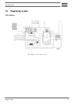
Page 17: ...Flow diagram of GA200 GA250 and GA315 60 Hz Instruction book 2920 1475 06 15 ...
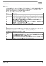
Page 30: ...Menu flow for GA 90 up to GA 315 simplified example Instruction book 28 2920 1475 06 ...
Page 57: ...Dimension drawing of GA90 110 water cooled Instruction book 2920 1475 06 55 ...
Page 60: ...Dimension drawing of GA200 250 and GA315 60 Hz air cooled Instruction book 58 2920 1475 06 ...
Page 64: ...Compressor room example of GA 90 up to GA 160 water cooled Instruction book 62 2920 1475 06 ...
Page 76: ...Suspended solids Non soluble particles size 1 mm 10 ppm Instruction book 74 2920 1475 06 ...
Page 98: ...Filler and drain plugs on GA 200 up to GA 500 compressors Instruction book 96 2920 1475 06 ...
Page 102: ...Position of oil filter on GA 200 up to GA 500 Instruction book 100 2920 1475 06 ...
Page 133: ...Instruction book 2920 1475 06 131 ...
Page 134: ......
Page 135: ......


