Compressor
Supply voltage
Cable size
GA 200
575 V
2x (3AWG2)
GA 250
440 - 460V
4x (3xAWG3/0+AWG3)
GA 250
575 V
2x (3AWG0)
GA 315
440 - 460V
4x (3xAWG4/0+AWG3)
GA 315
575 V
4x (3xAWG2/0+AWG4)
4.4
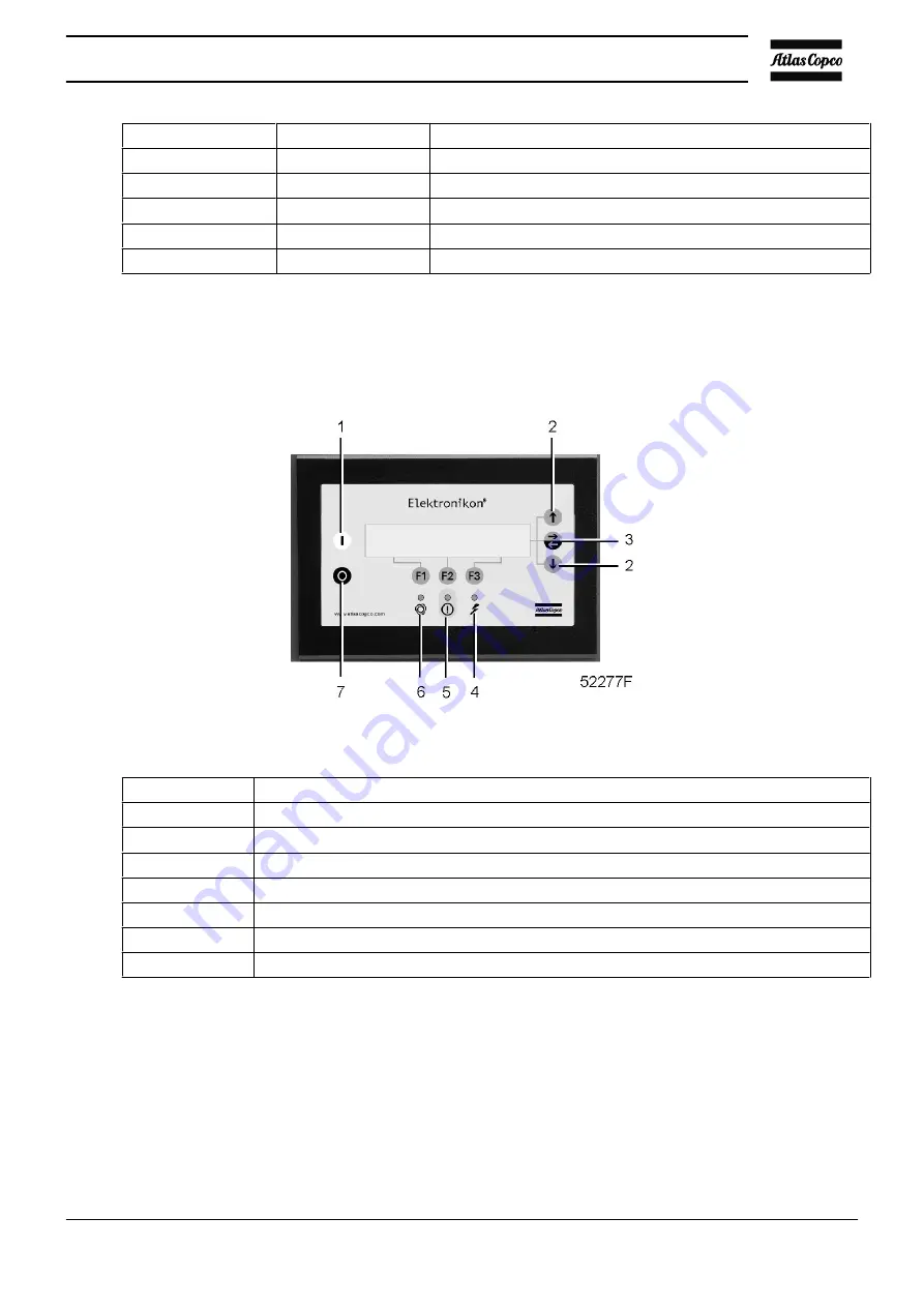
Pictographs
Control panel
Pictographs of control panel
Reference
Description
1
Start
2
Keys to scroll through display
3
Key to go to next field on display
4
Voltage on
5
Alarm
6
Automatic operation
7
Stop
Instruction book
2920 1475 06
69
Summary of Contents for GA110
Page 1: ...GA 90 GA 110 GA 132 GA 160 GA 200 GA 250 GA 315 ...
Page 2: ......
Page 17: ...Flow diagram of GA200 GA250 and GA315 60 Hz Instruction book 2920 1475 06 15 ...
Page 30: ...Menu flow for GA 90 up to GA 315 simplified example Instruction book 28 2920 1475 06 ...
Page 57: ...Dimension drawing of GA90 110 water cooled Instruction book 2920 1475 06 55 ...
Page 60: ...Dimension drawing of GA200 250 and GA315 60 Hz air cooled Instruction book 58 2920 1475 06 ...
Page 64: ...Compressor room example of GA 90 up to GA 160 water cooled Instruction book 62 2920 1475 06 ...
Page 76: ...Suspended solids Non soluble particles size 1 mm 10 ppm Instruction book 74 2920 1475 06 ...
Page 98: ...Filler and drain plugs on GA 200 up to GA 500 compressors Instruction book 96 2920 1475 06 ...
Page 102: ...Position of oil filter on GA 200 up to GA 500 Instruction book 100 2920 1475 06 ...
Page 133: ...Instruction book 2920 1475 06 131 ...
Page 134: ......
Page 135: ......


