11
2920 1190 05
Instruction book
Industrial Air Division
Ref.
Designation
Function
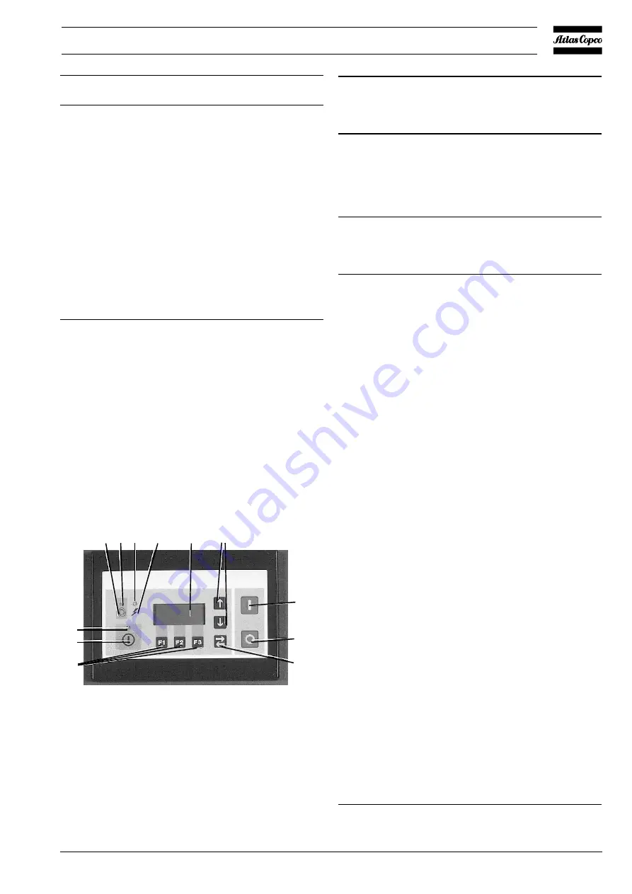
8
Start button
Push button to start the
compressor. LED (1) lights up
indicating that the regulator is
operative (in automatic operation).
9
Stop button
Push button to stop the
compressor. LED (1) goes out.
S0
Isolator switch
Switch to isolate the compressor
from the mains or to stop the
compressor immediately in case of
emergency. The compressor will
be depressurized automatically
when the isolator switch is
switched off.
1.4.2.1 General alarm LED (3-Fig. 7a) 1)
-
The LED blinks in case of a shut-down (due to too high a
compressor element outlet temperature, too high a motor
temperature, too high a temperature of the start and speed
control unit, overload of the fan motor, etc.); at the same
time the shut-down screen appears. After eliminating the
cause of the trouble and when the abnormal condition has
disappeared, press function key (5) below Rset.
-
The LED blinks and the compressor is shut down if the
sensor of the compressor element (TT11-Fig. 9b) is out of
order; at the same time the display will show a fault message.
Depressurize the compressor by switching off the isolator
switch, close the air outlet valve and open manual drain
valve. Check the sensor and its wiring.
-
The LED also blinks in case of a system failure (due to
hardware, software or communication problems). Consult
the "User manual for Elektronikon regulator" section
"System failures".
-
The LED is alight in case of a shut-down warning; at the
same time a warning message appears. Remedy; see section
6.
1.4.2.2 Selecting a menu
To facilitate controlling the compressor, menu-driven programs
are implemented in the Elektronikon module. Use the function
keys (5) to select the menus in order to program and monitor
the compressor. The "User manual for Elektronikon regulator"
deals elaborately with all regulator functions.
1) Consult the "User manual for Elektronikon regulator", section
"Status data submenu".
1.
LED, automatic
operation
2.
LED, voltage on
3.
LED, general alarm
4.
Display
5.
Function keys
6.
Scroll keys
7.
Tabulator key
8.
Start button
9.
Stop button
11. Pictograph, automatic
operation
12. Pictograph, voltage on
13. Pictograph, alarm
Fig. 7a. Control panel
Delivery air
bar
7.0
rpm
2500
Menu
More
F1
F2
F3
Fig. 7b. Example of the main display
Status data
Main
Slct
F1
F2
F3
Fig. 7c. Example of a main menu
Figs. 7. Displays
11 1 2 12 4 6
8
9
7
3
13
5
F029


