2920 1190 05
28
Industrial Air Division
Instruction book
4.6 Oil filter change (Figs. 12)
1. Close the air outlet valve (AV-Fig. 1) and let the compressor
run at minimum speed for 3 minutes. Stop the compressor,
switch off isolator switch (S0-Figs. 1 and 3a) and open
manual drain valve (Dm-Fig. 5). Wait until the
compressor has depressurized. Unscrew oil filler plug
(FC) only one turn to permit any pressure in the system
to escape.
2. Remove vent plug (VP-Figs. 3a and 4), wait 5 minutes,
remove the drain plug in the oil filter housing and catch the
oil in a receptacle.
3. Remove oil filter(s) (OF-Figs. 9b and 12a).
4. Clean the filter seat(s) on the manifold. Oil the gaskets of
the new elements. Screw the elements into place and tighten
them firmly by hand.
5. Fill the receiver (AR) with oil until the level reaches the
filler neck (adapter part included).
6. Tighten plug (FC). Tighten the plug in the oil filter housing
and vent plug (VP-Figs. 3a and 4).
7. Reset the oil filter service warning. 1)
4.7 Oil separator change
1. Stop the compressor, switch off the isolator switch, close
the air outlet valve (AV-Fig. 1) and open manual drain
valve (Dm-Fig. 5). Wait until the compressor has
depressurized. Unscrew oil filler plug (FC-Figs. 12) only
one turn to permit any pressure in the system to escape.
2. Disconnect the flexibles from the minimum pressure valve
(Vp-Fig. 12a) and air receiver cover.
1) Consult the "User manual for Elektronikon regulator", section
"Service submenu".
Example
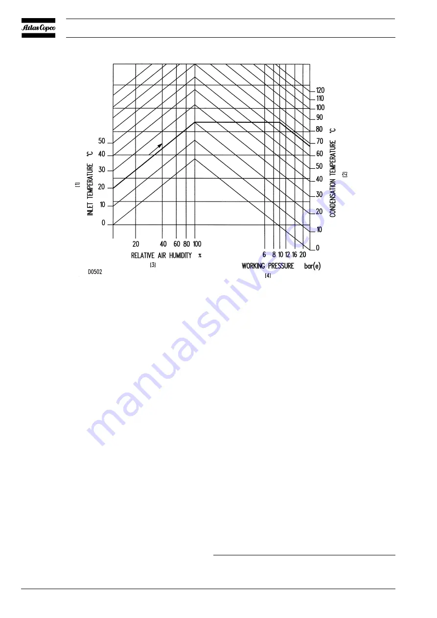
If operating at a pressure of 10 bar(e) in an ambient temperature of 20°C and at a relative air humidity of 100 %, the minimum
temperature to prevent condensate from forming is 68°C. Regulate the cooling water flow during loaded operation to obtain a
temperature between 70°C and approx. 75°C at the outlet of the compressor element.
Fig. 15. Minimum allowable air temperature at outlet of compressor element (water-cooled compressors only)


