Industrial Air Division
7
2920 5997 03
During loaded operation, the circuit to solenoid valve (Y1) is closed
preventing the compressed air from flowing to unloader (29).
When the pressure in air receiver (16) reaches the maximum or
unloading pressure, pressure switch (PSR19) de-energizes
solenoid valve (Y1). Compressed air from the receiver will flow via
the solenoid valve to the upper side of unloader plunger (30), which
opens unloader valve (34). The compressed air from the
compressor is now blown off to atmosphere through muffler (28).
Check valve (13) closes and prevents venting of the air receiver.
When the pressure in the air receiver decreases to the pre-set
loading or starting pressure, pressure switch (PSR19) closes the
circuit to solenoid valve (Y1); control air from the unloader plunger
chamber is vented to atmosphere. Unloader valve (34) closes,
check valve (13) opens and the compressed air is supplied to the
receiver again.
Install the compressor horizontally, in a cool but frost-free and well-
ventilated room. Place the compressor as level as possible;
however, it can be operated with an angular deviation below 15° in
any direction. The air should be clean.
A
Pack unit
must be installed away from walls to allow easy
maintenance. Keep the ventilation openings free.
A condensate drain facility must be installed downstream of the
compressor in the lowest part of the air net. If any further
information is required, consult Atlas Copco.
2.1 Electrical connections
The electrical installation must be carried out by an electrician and
correspond to the local codes.
The indications on the motor data plate must correspond to the
mains supply voltage and frequency. The mains supply and
earthing lines must be of suitable size. The installation must
include an isolating switch in the power line near to the unit and be
protected against short-circuits by fuses of the inert type in each
phase. In case the overload protection is not supplied with the unit,
a circuit breaker instead of an isolating switch and fuses must be
installed.
For LE/LT7 up to -12 and LEN
, connect the power supply to
terminals L1, L2 and L3 of line contactor (K1-Fig. 3). Connect the
earth conductor to connector (PE) and the neutral conductor (if
provided) to connector (N) on the terminal strip.
For LE/LT5, -6
,
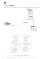
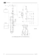
consult the electrical diagrams (Figs. 10 and 11).
The electrical diagram is stuck on or in the motor starter. The
diagram shows the electrical connections, the settings of the
overload relay and the maximum fuse rating with regard to the
short-circuit protection of the starter. The cable section used may
require fuses of a smaller value.
Never operate the unit without an earth conductor.
The selector switch (S1-Fig. 1d) on the motor starter (starter
equipped with hourmeter) permits the selection of two operating
modes, i.e. semi-automatic (1/2 AUTO) or fully automatic (AUTO)
operation.
Semi-automatic operation:
the motor runs without interruption.
The compressed air is either discharged into the receiver or blown
off to atmosphere, depending on the air consumption. This
operating mode is selected when the air consumption is more or
less steady and the total unloading time per hour comparatively
small.
Fully
automatic operation:
the electric motor stops and restarts
at the pre-set upper and lower limits of the air pressure switch
respectively. This operating mode is selected when the air
consumption is at times steady and at times irregular with long
interruptions.
The number of starts must not exceed 15 per
hour.
2 Installation
F1/2. Fuses, transformer (T1)
primary side
F3.
Fuse, transformer (T1)
secondary side
F4.
Motor overload relay
K1.
Line contactor
K1-1. Star-delta timer
K2.
Delta contactor
K3.
Star contactor
N.
Neutral conductor
connector
PE.
Earth conductor
connector
P1.
Hourmeter
S1.
ON-OFF/selector switch
T1.
Transformer
1.
Power supply terminals:
L1, L2 and L3
2.
Reset knob, overload
relay
Fig. 3. Detail of motor starter (typical example)
F1757
Summary of Contents for LE11
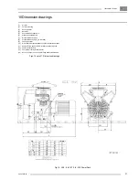
Page 22: ...IndustrialAirDivision 2920 5997 03 22 Fig 15 LE7 7N 8 8C LT7 8 730 Power Pack ...
Page 23: ...IndustrialAirDivision 23 2920 5997 03 Fig 16 LE9 9N 11 12 LT9 11 12 930 1230 Power Pack ...
Page 24: ...IndustrialAirDivision 2920 5997 03 24 Fig 17 LE5 6 6C LT5 6 Complete Unit ...
Page 25: ...IndustrialAirDivision 25 2920 5997 03 Fig 18 LE7 7N 8 8C LT7 8 Complete Unit ...
Page 26: ...IndustrialAirDivision 2920 5997 03 26 Fig 19 LE9 9N 11 12 LT9 11 12 Complete Unit ...
Page 28: ...IndustrialAirDivision 2920 5997 03 28 Fig 21 LE LT7 8 9 11 12 Pack ...


