Reference
Description
1
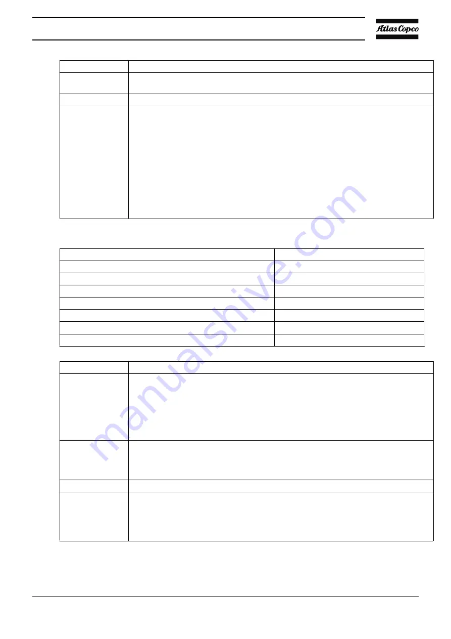
Install the compressor on a level floor suitable for taking its weight. Recommended
minimum distance between the top of the unit and the ceiling is 200 mm (7.87 inch).
2
Compressor air outlet valve (to be provided by the customer).
3
The pressure drop over the air outlet pipe can be calculated as follows:
It is recommended that the connection of the compressor air outlet pipe is made on top of
the main air net pipe in order to minimize carry-over of possible condensate residue.
As a rule of thumb, the following formula can be used to calculate the recommended
volume of the air net:
V = (30 x C x p x Q) / Dp
C = Correction factor
Dp = Pressure difference between unloading and loading pressures in bar
(recommended minimum = 0.6)
p = Compressor inlet pressure in bar absolute
Q = Free air delivery of compressor in l/s
V = Recommended air net volume in l
Correction factors
Air consumption divided by compressor free air delivery
Correction factor C
0.9
0.10
0.8
0.15
0.7
0.20
0.5
0.25
0.3
0.20
0.2
0.15
0.1
0.10
Reference
Description
4
The inlet grids and ventilation fan should be installed in such a way that any recirculation
of cooling air to the compressor is avoided. The maximum air velocity through the grids is
5 m/s (16.5 ft/s).
The maximum air temperature at the compressor intake opening is 46 °C (114.8 °F).
The minimum air temperature at the compressor intake opening is 0 °C (32 °F).
The required ventilation to limit the compressor room temperature can be calculated as
follows:
5
Drain pipes to condensate collector. The drain pipes may not enter in the collector.
Individual drain pipes may not be interconnected, to avoid interference.
Compressor condensate contains oil. Depending on local legislation it is recommended to
install an oil/water separator (consult Atlas Copco).
6
Control cubicle with monitoring panel.
7
Main cable entry.
See section
for the recommended size of the supply cables.
Check that the electrical connections correspond to the local codes. The installation must
be earthed and protected against short circuits by fuses in all phases. An isolating switch
must be installed near the compressor.
Instruction book
APF219617
45
Summary of Contents for MAS 200
Page 1: ...Instruction book APF219617 MAS 200 ...
Page 2: ......
Page 44: ...Instruction book 42 APF219617 ...
Page 49: ...Electric connections Electrical diagram Instruction book APF219617 47 ...
Page 92: ......
Page 93: ......


