Elektronikon settings
The loading and unloading pressure settings of the Elektronikon should comply with the following
rules:
• The unloading pressure should be at least 0.2 bar higher than the set pressure of the
modulating control valve.
• The loading pressure should be at least 0.2 bar lower than the set pressure of the
modulating control valve.
• The difference between loading and unloading pressure should be sufficient to have a stable
operation of the unit, i.e. the compressor should never switch more than once per minute
from load to unload.
• The unloading pressure of the Elektronikon should be :
• Or lower than 10 bar,
• Or lower than 0.5 bar above the set pressure of the control valve (in order to limit the
control pressure that is fed in the throttle valve to 10 bar)
7.7
Modulating control : System components
Control valve
The control valve has one air input.
The set pressure of the control valve is manually adjustable between 5 and 13 bar. Turning the
hand wheel of the control valve clockwise increases the set pressure. By turning the hand wheel
counterclockwise, the set pressure will decrease.
The control valve has one control air output. The control valve always works in conjunction with a
bleed-off nozzle.
An example of the relationship between air input and control air output (with a bleed-off nozzle
with diameter 1 mm), i.e. the relationship between net pressure and control pressure, is given in
the table below.
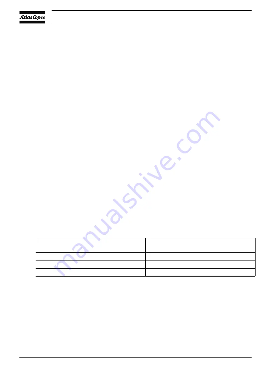
Relationship between input and output pressure of the control valve
Inlet pressure P
in
(= net pressure)
Output pressure P
out
(= control pressure)
(within 5 s after change in P
in
)
0 bar ≤ P
in
< (P
set
- 0.3 bar)
P
out
< 1 bar
(P
set
- 0.3 bar) < P
in
< (P
set
+ 0.3 bar)
ΔP
out
/ΔP
in
> 0
P
in
> (P
set
+ 0.3 bar)
P
out
> 4 bar
Bleed-off nozzle
The bleed-off nozzle has a calibrated cylindrical hole with a diameter of 1 mm.
The diameter of the bleed-off nozzle determines the width of the pressure band. A smaller
diameter will decrease the width of the pressure band but at the same time will make the control
system less stable due to the larger feedback amplification factor.
Throttle valve
The throttle valve is a pneumatically operated butterfly valve with by-pass hole(s).
Instruction book
84
APF219617
Summary of Contents for MAS 200
Page 1: ...Instruction book APF219617 MAS 200 ...
Page 2: ......
Page 44: ...Instruction book 42 APF219617 ...
Page 49: ...Electric connections Electrical diagram Instruction book APF219617 47 ...
Page 92: ......
Page 93: ......


