background image

Connections for external compressor status indication

Terminal strip (1X7) is provided with auxiliary contacts for external indication of:

Indication

Relay

Terminals on strip 1X7

Maximum load

Automatic operation

K05-1

11-12

10 A / 230 V AC

General Warning

K06-1

13-14

10 A / 230 V AC

General Shut-down

K07-1

15-16

10 A / 230 V AC

Loaded-Unload

K11

17-18

3 A / 230 V AC

Motor running

K21

19-20

6 A / 230 V AC

Remote control from
module

K10-1

21-22

--

4.6

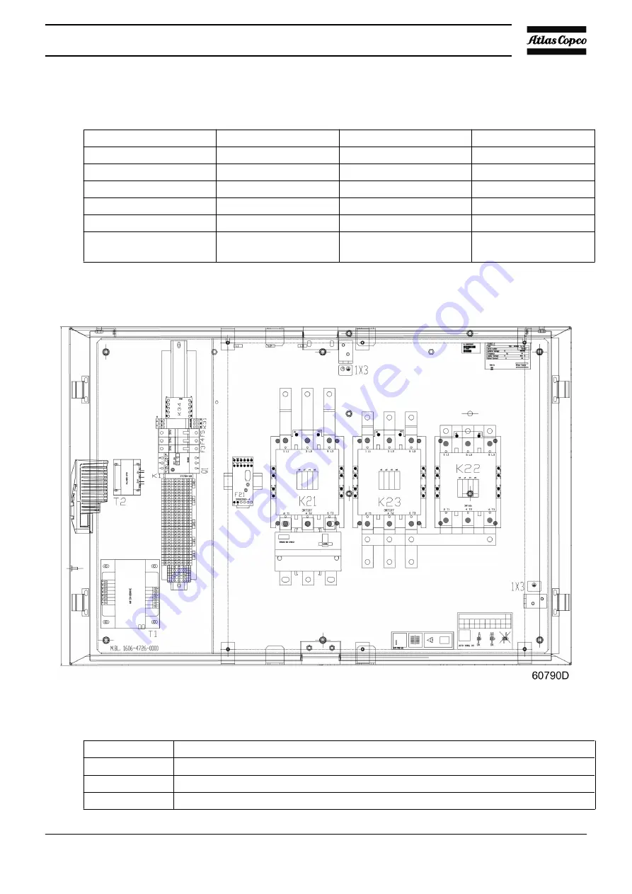
Position of components

Electric cabinet, Y-D starter

Ref.

Description

F3–5

Circuit breakers, control circuit

F21

Overload relay of compressor motor

K21

Line contactor

Instruction book

APF219617

49

Summary of Contents for MAS 200

Page 1: ...Instruction book APF219617 MAS 200 ...

Page 2: ......

Page 3: ...thereof is prohibited This applies in particular to trademarks model denominations part numbers and drawings This instruction book is valid for CE as well as non CE labelled machines It meets the requirements for instructions specified by the applicable European directives as identified in the Declaration of Conformity 2017 08 www atlascopco com ...

Page 4: ...INTRODUCTION 11 2 2 AIR AND OIL SYSTEM 14 2 3 COOLING AND CONDENSATE SYSTEM 16 2 4 REGULATING SYSTEM 16 2 5 MODULATING CONTROL SYSTEM 17 3 Elektronikon Graphic controller 20 3 1 ELEKTRONIKON GRAPHIC CONTROLLER 20 3 2 DIGITAL OUTPUT CONTACTS 22 3 3 ICONS USED 23 3 4 MAIN SCREEN 27 3 5 CONTROLLER MENU STRUCTURE 31 3 6 WEB SERVER 34 4 Installation 43 4 1 DIMENSION DRAWING 43 4 2 INSTALLATION PROPOSAL...

Page 5: ... 61 5 5 DURING OPERATION 63 5 6 CHECKING THE DISPLAY 64 5 7 MANUAL LOADING UNLOADING 65 5 8 STOPPING 65 5 9 TAKING OUT OF OPERATION 66 5 10 USE OF AIR RECEIVER 67 6 Maintenance 68 6 1 PREVENTIVE MAINTENANCE SCHEDULE 68 6 2 MOTORS 70 6 3 OIL SPECIFICATIONS 70 6 4 OIL AND OIL FILTER CHANGE 71 6 5 MODULATING CONTROL 76 6 6 STORAGE AFTER INSTALLATION 77 6 7 SERVICE KITS 77 7 Adjustments and servicing ...

Page 6: ...STING THE SET PRESSURE OF THE CONTROL VALVE 83 7 7 MODULATING CONTROL SYSTEM COMPONENTS 84 8 Problem solving 86 8 1 PROBLEM SOLVING 86 9 Technical data 88 9 1 SAFETY VALVE 88 9 2 SETTINGS FOR OVERLOAD RELAY AND FUSES 88 9 3 SETTINGS OF CIRCUIT BREAKERS 88 9 4 COMPRESSOR DATA 89 Instruction book 4 APF219617 ...

Page 7: ...f the voltage Depressurize the machine Lock Out Tag Out LOTO Open the power isolating switch and lock it with a personal lock Tag the power isolating switch with the name of the service technician On units powered by a frequency converter wait 10 minutes before starting any electrical repair Never rely on indicator lamps or electrical door locks before maintenance work always disconnect and check ...

Page 8: ...siccant bags must be removed before connecting the pipes 5 Air hoses must be of correct size and suitable for the working pressure Never use frayed damaged or worn hoses Distribution pipes and connections must be of the correct size and suitable for the working pressure 6 In case the device is a compressor the aspirated air must be free of flammable fumes vapors and particles e g paint solvents th...

Page 9: ...ystem is present in the air net close to the dryer safety valves must be installed in the vessels of the dryer Also consult following safety precautions Safety precautions during operation and Safety precautions during maintenance These precautions apply to machinery processing or consuming air or inert gas Processing of any other gas requires additional safety precautions typical to the applicati...

Page 10: ... tamper with the sound damping material 12 Never remove or tamper with the safety devices guards or insulations fitted on the machine Every pressure vessel or auxiliary installed outside the machine to contain air above atmospheric pressure shall be protected by a pressure relieving device or devices as required 13 Yearly inspect the air receiver Minimum wall thickness as specified in the instruct...

Page 11: ...with open flame for inspecting the interior of a machine pressure vessel etc 14 Make sure that no tools loose parts or rags are left in or on the machine 15 All regulating and safety devices shall be maintained with due care to ensure that they function properly They may not be put out of action 16 Before clearing the machine for use after maintenance or overhaul check that operating pressures tem...

Page 12: ...in the previous chapters to secure safe handling e g LOTO cool down depressurize discharge 3 Separate the harmful from the safe components e g drain oil from oil containing parts 4 Refer to the disposal topic mentioned below Disposal Used filters or any other used material e g desiccant lubricants cleaning rags machine parts etc must be disposed of in an environmentally friendly and safe manner an...

Page 13: ...Introduction General The unit is a single stage water cooled oil injected screw compressor driven by an electric motor The intended use of the compressor is onboard of a seagoing vessel General view Instruction book APF219617 11 ...

Page 14: ...nual condensate drain valve 6 Compressed air outlet 13 Aftercooler 20 Water separator 7 Manual automatic condensate drain outlets 14 Oil Cooler The compressor is delivered without a sound insulated bodywork and includes mainly Air filter Compressor element Air receiver oil separator Oil coolers Drive motor Gear casing Unloader Elektronikon control system Safety devices Phase Sequence Relay The pha...

Page 15: ...nd connected to the control panel An indicator lamp indicates that the heaters are on off When the compressor is stopped the heaters are automatically switched on The heaters in the motor will prevent condensation during stand still The heater includes the anti condensation power supply and its control Pipe connections DIN connections for flanges ISO for threaded pipes or pipe couplings Modulating...

Page 16: ...2 2 Air and oil system Flow diagram Reference Description 1 Atlas Copco installation 2 Customer installation 46 Modulating control 100 Air filter Instruction book 14 APF219617 ...

Page 17: ...2 Compressed air and oil are discharged through check valve 104 to air receiver oil separator 106 where oil is separated from the compressed air The air is blown through minimum pressure valves 109 to aftercooler 110 The cooled air is discharged through condensate trap 111 and the air outlet towards the air net Check valve 104 prevents blow back of compressed air Minimum pressure valve 109 prevent...

Page 18: ...ate and with a manual drain valve 2 4 Regulating system Reference Designation A To air cooler B To from oil cooler The compressor is controlled by the Elektronikon regulator see section Elektronikon controller The regulator keeps the net pressure within programmable pressure limits by automatically loading and unloading the compressor depending on the air consumption It also protects the compresso...

Page 19: ...n the net pressure decreases to the lower limit of the working pressure loading pressure solenoid valve 5 is energized The plunger of solenoid valve 5 moves upwards against spring force Phase 1 The plunger of solenoid valve 5 opens the supply of receiver pressure towards chamber 2 Unloading valve 7 opens against spring force 2 Receiver pressure also pushes valve 9 upwards shutting off blow off cha...

Page 20: ...ease accordingly and the throttle valve will close This will result in a decrease in absolute pressure at the inlet of the compressor element and consequently in a decrease in air delivery reducing fluctuations in net pressure An increase in air demand will result in the same way in an increase in air delivery This will result in a net pressure staying within a narrow band To protect the compresso...

Page 21: ...l the unload pressure is reached and the Elektronikon will unload the compressor as on a standard compressor With a continuing air demand the net pressure will then drop until the load pressure is reached and the Elektronikon will let the compressor run loaded Instruction book APF219617 19 ...

Page 22: ...with frequency converter A number of programmable settings e g the unloading and loading pressures for fixed speed compressors the setpoint for compressors with frequency converter the minimum stop time and the maximum number of motor starts and several other parameters are hereby taken into account The controller stops the compressor whenever possible to reduce the power consumption and restarts ...

Page 23: ...s Warning A warning message will appear if on Full Feature compressors the dew point temperature is too high in relation to the ambient temperature Service warning A number of service operations are grouped called Service Plans Each Service Plan has a programmed time interval If a time interval is exceeded a message will appear on display 1 to warn the operator to carry out the service actions bel...

Page 24: ...n Mk5 always comes with expansion module IO2 that has a number of digital output contacts which can be used to connect external equipment Depending on the optional equipment extra expansion modules are added to the machine configuration IO2 IO34 Expansion Module IO2 for Elektronikon Mk5 The digital output contacts have following specifications Relay Connector Maximum load K01 3 X 31 15 A 250 V AC ...

Page 25: ...e load K10 3 X 32 10 A 250 V AC 10 A 30 V DC resistive load K11 3 X 32 10 A 250 V AC 10 A 30 V DC resistive load K12 3 X 32 10 A 250 V AC 10 A 30 V DC resistive load K13 3 X 32 10 A 250 V AC 10 A 30 V DC resistive load K14 3 X 32 10 A 250 V AC 10 A 30 V DC resistive load K15 3 X 32 10 A 250 V AC 10 A 30 V DC resistive load Resistor Capacitor 3 3 Icons used Status icons Name Icon Description Stoppe...

Page 26: ...op Network control Automatic restart after voltage failure Automatic restart after voltage failure is enabled Week timer Week timer is active Active protection functions Emergency stop Shutdown Warning Service Service required Error Main screen Displayed when 2 or 4 line layout is picked Instruction book 24 APF219617 ...

Page 27: ... is picked Menu icons Icon Description Service Alarms warnings shutdowns Week timer Info Test Counters Regulation setpoints Inputs Outputs Event history saved data Settings Input icons Icon Description Pressure Instruction book APF219617 25 ...

Page 28: ...d Special protection System icons Icon Description Automatic restart ARAVF Main chart Compressor element LP HP Filter s Motor Expansion module Network settings problem General alarm Oil circuit Regulation General settings Instruction book 26 APF219617 ...

Page 29: ...n Description Up Down 3 4 Main screen Control panel Control panel 1 Enter key 2 Cancel Escape key 3 Scroll keys Function The main screen shows the status of the compressor and is the gateway to all functionality implemented in the controller Instruction book APF219617 27 ...

Page 30: ...ection A displays information regarding the compressor operation e g outlet pressure temperature at compressor outlet Section B displays Status icons Following icon types are shown in this field Fixed icons These icons are always shown in the main screen and cannot be selected by the cursor e g Compressor stopped or running Shortcut icons These icons are always shown in the main screen If the icon...

Page 31: ...ing the scroll keys and push the Enter key Section C is called the Status bar This bar shows the text that corresponds to the selected icon Section D shows the Action buttons These buttons are used to call up or program settings to reset a shutdown service message or emergency stop to have access to all data collected by the controller The function of the buttons depends on the displayed menu The ...

Page 32: ...isplay is selected a chart with an X axis covering 4 hours is displayed The value displayed on the Y axis depends on the selection made in the input screen Each chart dot represents a 1 minute average value When the Chart Low Resolution display is selected a chart with an X axis covering 10 days is displayed The value displayed on the Y axis depends on the selection made in the input screen Each c...

Page 33: ...ervice plans Service Plan Displays configuration of the service plans Next Service Displays the next service task History Displays a log of all automatic shutdowns that have appeared in the past PROTECTIONS Topic Description General Displays a list of main protections Filter s Displays a list of filter protections Expansion module Displays a list of protections of the expansion module communicatio...

Page 34: ...mber of hours the compressor has been running in unloaded loaded mode Loaded Hours Displays the number of hours the compressor has been running in loaded mode Motor Starts Displays the number of motor starts Load Relay Displays the number of load relay toggles thus unload load transitions Fast Starts Displays the number of manual motor starts that exceed the automatic motor starts Module Hours Dis...

Page 35: ...escription General Displays a number of analogue and digital outputs Main Motor Displays a number of digital outputs concerning the main motor status SPM Shock Pulse Method Topic Description Motor drive end Displays the vibration level at the drive end of the motor Motor non drive end Displays the vibration level at the non drive end of the motor Low pressure stage drive end Displays the vibration...

Page 36: ...remote control mode Password protected Main Motor Displays the settings of the main motor 3 6 Web server All controllers have a built in web server that allows direct connection to the company network or to a dedicated PC via a local area network LAN This allows to consult certain data and settings via a PC instead of the display of the controller Getting started Make sure you are logged in as adm...

Page 37: ...oller Click with the right button and select Properties 1 Use the check box Internet Protocol version 4 TCP IPv4 1 see picture To avoid conflicts uncheck other properties if they are checked After selecting TCP IPv4 click on the Properties button 2 to change the settings Instruction book APF219617 35 ...

Page 38: ...o generate a fixed IP address in your company s network That IP address will be excluded from the DNS server so it will be reserved for the controller Also get the correct Gateway and Subnet mask settings For example IP 10 25 43 200 Gateway 10 25 42 250 Subnet mask 255 255 254 0 Connect the controller to the company s network LAN by using a UTP cable min CAT 5e Instruction book 36 APF219617 ...

Page 39: ... Adapt the network settings in the controller Go to Main Menu Go to Settings 1 Go to Network 1 Instruction book APF219617 37 ...

Page 40: ... Ethernet 1 Switch Off 1 the Ethernet communication to allow editing the settings Adapt IP Address 1 Adapt Gateway IP 2 Adapt Subnet Mask 3 Switch On 4 the Ethernet communication Instruction book 38 APF219617 ...

Page 41: ... Also Opera Mozilla Firefox Safari and Chrome should work Viewing the controller data All screen shots are indicative The number of displayed fields depends on the selected options Open your browser and type the IP address of the controller you want to view in your browser in this example http 192 168 100 100 The interface opens Screen shot example Instruction book APF219617 39 ...

Page 42: ... if a license is provided Preferences allows to change temperature and pressure unit Unit settings All unit settings can be displayed or hidden Put a check mark in front of each point of interest and it will be displayed Only the machine status is fixed and can not be removed from the main screen Analog inputs Lists all current analog input values The measurement units can be changed in the prefer...

Page 43: ...ts Lists all digital outputs and their status Special protections Lists all special protections of the unit Service plan Displays all levels of the service plan and their status This screen shot underneath only shows the running hours It is also possible to show the current status of the service interval Instruction book APF219617 41 ...

Page 44: ...Instruction book 42 APF219617 ...

Page 45: ...ate 3 With modulating control 4 4 slotted holes for horizontally pulling unit out of container No hoisting 5 With fully open doors 6 Maintenance separator 7 Manual drain 8 Automatic drain 9 Compressor outlet 10 Cooling water inlet 11 Cooling water outlet 12 Centre of gravity 13 Type Instruction book APF219617 43 ...

Page 46: ...le General installation Holes in the cubicle which are not used should be plugged All electric screens in the control cubicle and drive cubicle have to be installed before start up and remain installed during operation Instruction book 44 APF219617 ...

Page 47: ... 0 25 0 3 0 20 0 2 0 15 0 1 0 10 Reference Description 4 The inlet grids and ventilation fan should be installed in such a way that any recirculation of cooling air to the compressor is avoided The maximum air velocity through the grids is 5 m s 16 5 ft s The maximum air temperature at the compressor intake opening is 46 C 114 8 F The minimum air temperature at the compressor intake opening is 0 C...

Page 48: ...stalled between the compressor water outlet pipe and the shut off valve When operating the unit the operator must ensure that the cooling water system cannot be blocked 9 Cooling water outlet pipe 10 Motor ventilation air inlet 11 Compressor air inlet See the compressor installation manual for more information All pipes must be installed stress free to the compressor unit For maintenance purpose t...

Page 49: ...Electric connections Electrical diagram Instruction book APF219617 47 ...

Page 50: ...ality of safety components When installing a remote emergency button or a motor contactor the following B10d values are advised Emergency stop button 500 000 Main contactor 1 333 333 4 5 External compressor status indication Warning Stop the compressor and switch off the voltage before connecting external equipment Consult the Safety precautions Instruction book 48 APF219617 ...

Page 51: ...11 12 10 A 230 V AC General Warning K06 1 13 14 10 A 230 V AC General Shut down K07 1 15 16 10 A 230 V AC Loaded Unload K11 17 18 3 A 230 V AC Motor running K21 19 20 6 A 230 V AC Remote control from module K10 1 21 22 4 6 Position of components Electric cabinet Y D starter Ref Description F3 5 Circuit breakers control circuit F21 Overload relay of compressor motor K21 Line contactor Instruction b...

Page 52: ...cable lugs Spacing of 10 mm between naked cable parts should be obtained Copper conductors with a 95 C isolation class should be applied Model Motor voltage V Fuse selection A FLA A Recommended cable size mm Cable length m Cable size mm Cable length m MAS 200 440 2x 3x 250 365 2x 3x 120 70 284 4x 3x 50 25 147 MAS 200 480 2x 3x 250 347 2x 3x 120 70 310 4x 3x 50 25 160 FLA Full Load Ampacity 4 8 Pic...

Page 53: ... Cooling water outlet 14 Automatic condensate drain 15 Manual condensate drain 16 Ear protectors obliged 17 Helmet obliged 18 Warning under tension 19 Switch off the voltage before removing the protecting cover inside the electric cabinet 20 Roto Xtend Duty Fluid Do not mix oil brands 21 Warning heated surface 22 Stop the compressor before maintenance or repair 23 Read Instruction book before star...

Page 54: ...rculating system with a cooling tower In the latter case the composition of the water that enters the cooler must be considered and not the composition of the make up water Due to the evaporative effect in the cooling tower much higher concentrations of ions can be obtained in the circulating water than in the make up water Ryznar stability index RSI The Ryznar Stability Index RSI is a parameter f...

Page 55: ...8 38 44 1 7 70 87 1 5 1 40 1 76 1 9 45 50 1 6 88 110 1 6 1 78 2 20 2 0 51 56 1 5 111 138 1 7 2 22 2 78 2 1 57 63 1 4 138 174 1 8 2 80 3 54 2 2 64 71 1 3 175 220 1 9 3 54 4 40 2 3 72 80 1 2 230 270 2 0 4 6 5 4 2 4 280 340 2 1 5 6 7 0 2 5 350 430 2 2 7 2 8 8 2 6 440 550 2 3 9 0 11 0 2 7 560 690 2 4 11 2 13 8 2 8 700 870 2 5 14 0 17 6 2 9 880 1000 2 6 17 8 20 0 3 0 Interpretation of the value obtaine...

Page 56: ...tations 6 8 pH Total dissolved solids TDS This is the sum of all the ions in the water It can be derived from the dry residue after evaporation but not including suspended solids or it can be estimated from the electrical conductivity In a closed system the following limits apply TDS 3000 mg l 3800 microS cm For an open system the following limits apply TDS 450 mg l 580 microS cm Chlorides Cl Chlo...

Page 57: ...50 1000 ppm CaCO3 Open cooling system 50 500 ppm CaCO3 HCO3 SO4 2 should be 1 Ammonia 0 5 ppm Copper 1 ppm Iron and manganese 1 ppm Organics No algae No oil Suspended solids Non soluble particles size 1 mm 10 ppm Instruction book APF219617 55 ...

Page 58: ...sor can be moved by a lift truck using the slots in the frame Make sure that the forks protrude from the other side of the frame The compressor can also be lifted after inserting beams in the slots Make sure that the beams cannot slide and that they protrude from the frame equally The chains must be held parallel to the bodywork by chain spreaders in order not to damage the compressor The lifting ...

Page 59: ...ile Corrosion Inhibitor plates are provided inside the bodywork to protect the compressor against corrosion Remove the plates 4 For initial start up or if the compressor has not run for the past 6 months it is required to improve the lubrication of the compressor element before starting Fill up the compressor element as described in section Oil and oil filter change 5 Check that the compressor is ...

Page 60: ...switch must be fitted 2 Check the wires on transformers for correct connection 3 Check the setting of the circuit breakers see section Settings of circuit breakers 4 Measure the supply voltage before initial start up for allowable tolerances see section Limits 5 Check that overload relay F21 is set for automatic resetting and check its setting see section Settings for overload relay and fuses Wate...

Page 61: ...or look at the fan through the grating at the non drive end of the motor The correct rotation direction is indicated by an arrow on the gear casing 4 If the rotation direction is wrong press the emergency stop button switch off the voltage and reverse two incoming electric lines 5 Run the compressor for a few minutes and check that it is operating normally 5 2 Before starting Warning The operator ...

Page 62: ...k signal from the generator closed ready is connected to an additional digital input on the Elektronikon module programmed as permissive start function When this input is OK within 60 seconds the unit will start Contact connected between 1X6 53 63 At standstill Start Request contact closed compressor can start no general warning Start Request contact open compressor will NOT start general warning ...

Page 63: ...failure if contact is closed during this preset time compressor starts and general warning disappears Compressor running Start Request contact closed or open no general warning Compressor stops Same situation as during standstill 5 4 Starting Warning The operator must apply all relevant Safety precautions Control panel Instruction book APF219617 61 ...

Page 64: ...with the compressor running loaded Adjust the water flow to obtain the most suitable air temperature at the outlet of the compressor elements The temperature must be between 2 and approx 7 C 3 6 and approx 12 6 F above the relevant temperature in the diagram Minimum allowable air temperature at outlet of the compressor element s Reference Name A Air inlet temperature in C B Condensation temperatur...

Page 65: ... number of motor starts Observe an interval of minimum 6 minutes between each manual start 5 5 During operation Warning The operator must apply all relevant Safety precautions The operator should immediately stop the machine in case of oil leaks internally in the machine as well as externally and consult a competent technician to resolve the cause The machine should not be restarted before the pro...

Page 66: ...button and switch off the voltage Close the air outlet valve and open the manual condensate drain valve Control panel Step Action 1 Regularly check the display for readings and messages Normally the main display is shown 2 Always check the display and remedy the trouble if alarm LED 4 is alight or blinks 3 The display will show a service message if a service plan interval has been exceeded or if a...

Page 67: ...hts up The Load command does not force the compressor into loaded condition but it will switch the compressor to automatic operation again the compressor will be loaded if the air net pressure drops below the programmed level 5 8 Stopping Important After pressing stop button 13 the compressor will run unloaded for 30 seconds The compressor stops after this period A start command during this period...

Page 68: ...t pipes customer s installation 6 Switch off the voltage 5 9 Taking out of operation Disconnecting the compressor At the end of the service life of the compressor proceed as follows Step Action 1 Stop the compressor and close the air outlet valve 2 Switch off the voltage Disconnect the compressor from the mains 3 Depressurize the compressor by opening the condensate drain valve and loosening the o...

Page 69: ...htened with a torque of 355 Nm 85 Nm Damaged bolts must not be re used O rings must be replaced 5 The safety valve is designed in such a way that the pressure will not permanently exceed the maximum allowable operating pressure of the vessel except for short pressure surges up to 1 1 times the design pressure 6 Only use oil specified by the manufacturer 7 Make sure the vessel is fully depressurise...

Page 70: ...rs 1 Operation Daily 8 Check readings on display Daily 8 Check that condensate is discharged during loading Daily 8 Check oil level Before starting the level should be in the middle of the sight glass Weekly Check the cleanliness of the cubicle filters Replace or clean if dusty 3 Monthly Clean compressor 3 Monthly Operate safety valve 3 Monthly Remove dismantle and clean float valve of condensate ...

Page 71: ...ed and preferably with a stable working pressure Damaged flexibles must be replaced immediately The schedule contains a summary of the maintenance instructions Read the related section before taking maintenance measures Any leak should be attended to immediately The longer interval checks must also include the shorter interval checks Service agreements Atlas Copco Customer Centres have a range of ...

Page 72: ... Roto Glide Amber 1300 70 1300 40 M3BP 355 SMA 2 Roto Glide Amber 600 35 600 35 M3BP 355 SMC 2 Roto Glide Amber 600 35 600 35 Roto Glide Amber ordering number is 2901 0338 03 400 g cartridge It is advisable to add grease while the motor is RUNNING Run in the motor for at least 1 hour after every regreasing Never mix greases of different brands or types 6 3 Oil specifications Atlas Copco Roto Xtend...

Page 73: ...Important Never mix oils of different brands or types 6 4 Oil and oil filter change Warning The operator must apply all relevant Safety precautions Procedure Instruction book APF219617 71 ...

Page 74: ...system is released 4 Loosen the vent plugs on the oil coolers 5 Unbind the oil drain hose 4 6 Guide the drain plug of the hose above a suitable container 7 Remove the drain plug out of the hose and drain the oil Compressor element 1 Unloader 5 Compressor element 2 Oil drain plug compressor element 6 Position of gearbox oil drain flexible and drain plug 3 Oil drain plug oil stop valve 7 Check valve...

Page 75: ...s into place until the gaskets contact their seats Then tighten by hand Filling the compressor element with oil Air inlet 1 Remove filler plug 1 2 Pour 1 l 0 26 US gal 0 22 Imp gal 0 04 cu ft of oil into the compressor element 3 Reinstall filler plug 1 after filling the element Filling the air receiver with oil 1 Reinstall and tighten the oil drain plug of the air receiver Instruction book APF2196...

Page 76: ... the oil filler plug again and top up the air receiver with oil until the level indicator reaches the right level pointer in the green range 9 Tighten the oil filler plug 10 After carrying out the service actions of the related service plan the service warning must be reset Resetting the service warning Control panel Resetting the Elektronikon regulator After carrying out all service actions in th...

Page 77: ...ter key Following screen appears 3 On the Service menu move the cursor to the action button Overview and press the enter key Following screen appears 4 On the Overview menu move the cursor to the action button Reset and press the enter key The timer is reset to 0 Instruction book APF219617 75 ...

Page 78: ...replaced each year If when inspected it shows any signs of wear it should also be replaced Actuating cylinder Before disassembling the actuating cylinder the compressor has to be completely depressurized and isolated from the air net Disconnect the flexible coming from the water separator Rod 3 should be clamped between soft beaks of a vice whilst disassembling as spring 5 is mounted under tension...

Page 79: ...out running from time to time protective measures must be taken Consult the Atlas Copco Customer Centre 6 7 Service kits General Service kits comprise all parts needed for servicing components and offer the benefits of genuine Atlas Copco parts while keeping the maintenance budget low All standard service kits are indicated in the relevant Parts Lists Service kits of special parts will not be supp...

Page 80: ...r filters Warning Stop the compressor close the air outlet valve press the emergency stop button and switch off the voltage The operator must apply all relevant Safety precautions Control panel Position of air filters Instruction book 78 APF219617 ...

Page 81: ...he voltage The operator must apply all relevant Safety precautions Procedure Keep the coolers clean to maintain the cooling efficiency If it should be necessary to wash the coolers with a cleaning agent consult Atlas Copco Customer Centre 7 3 Oil separator element Stop the compressor press the emergency stop button and switch off the voltage Close the air outlet valve and open the manual condensat...

Page 82: ...of safety valve 7 5 Motor current readout General This compressor is equipped with a current meter to measure the main motor current This current can be checked on the controller This current can also be read through a 4 20 mA signal Notes The measuring device is located within the motor s delta configuration The controller will calculate and display the corresponding supply current Preparation Tw...

Page 83: ... value shown on the Mk5 display The measured current may differ depending on where the measurement is done and how many parallel cables are installed When measuring within the motor delta circuit multiply by 1 73 Multiply by the number of parallel cables Always turn off the supply power before adjusting the dials on F21 The dial settings on F21 determine the motor overload protection Do not change...

Page 84: ... 207 12 8 161 72 A Multiply by 1 73 The supply current 280 1 A 16 8 mA 16 8 4 x 207 12 8 207 A Multiply by 1 73 The supply current 358 5 A Optional analog output Electronic overload relay with analog output expansion module 3RB2985 2AA0 2AB1 and 2AA1 4 to 20 mA 1 x Ie 0 128 mA Example Iout 10 40 mA Ie 6 0 A I 50 of Ie Imotor 3 0 A Instruction book 82 APF219617 ...

Page 85: ...ghtening it Start the compressor Throttle the outlet of the compressor until the outlet pressure is 10 higher than the desired set pressure Screw the hand wheel counterclockwise until the outlet pressure is 0 05 bar lower than the desired set pressure Screwing the hand wheel clockwise will increase the desired set pressure and thus increase the unit s outlet pressure Pushing the hand wheel back do...

Page 86: ... clockwise increases the set pressure By turning the hand wheel counterclockwise the set pressure will decrease The control valve has one control air output The control valve always works in conjunction with a bleed off nozzle An example of the relationship between air input and control air output with a bleed off nozzle with diameter 1 mm i e the relationship between net pressure and control pres...

Page 87: ...the cylinder rod will extract and through a crank open the butterfly valve At 1 bar control pressure the throttle valve should be fully open At 4 bar control pressure the throttle valve should be completely closed except for the by pass hole s Instruction book APF219617 85 ...

Page 88: ...essor and carry out the indicated service actions Reset the message see section Service menu A shut down warning message appears on the display 1 The alarm LED 4 will light up indicating that a shut down level is almost reached e g when the temperature at the outlet of the compressor elements becomes too high The message disappears as soon as the cause of the problem is remedied Unit is shut down ...

Page 89: ...ly clean and check Condition Fault Remedy Compressor air delivery or pressure below normal Air consumption exceeds air delivery of compressor Check equipment connected Choked air filters Replace filters Air leakage Check and correct Condition Fault Remedy Compressor element outlet temperature or delivery air temperature above normal Oil level too low Check and correct Oil coolers clogged Consult s...

Page 90: ...ve can be tested on a separate compressed air line Consult your Atlas Copco Customer Centre if the valve does not open at the correct pressure see section Settings of safety valve 9 2 Settings for overload relay and fuses Model Power kW Voltage V Nominal current of main motor A F21 A MAS 200 227 440 359 207 MAS 200 230 480 341 197 9 3 Settings of circuit breakers Circuit breaker Setting A Q1 2 5 Q...

Page 91: ...d A weighted sound pressure uncertainty in accordance with Clause 8 of EN ISO 2151 2008 dB 3 L WAd the declared A weighted sound power level where the A weighted emission sound pressure level at the workstation exceeds 80 dB A dB A 108 K WAd the associated uncertainty in accordance with Clause 8 of EN ISO 2151 2008 dB 3 Instruction book APF219617 89 ...

Page 92: ......

Page 93: ......

Page 94: ...ke performance stand the test of time This is what we call Sustainable Productivity Atlas Copco Airpower Oil free Air Division Boomsesteenweg 957 2610 Wilrijk Belgium Phone 32 0 3 870 21 11 Atlas Copco Airpower NV All rights reserved Designs and specifications are subject to change without notice or obligation ...

Reviews: