12
PAGE
Repair Instructions Nr.183.09/00
PHE 50 S
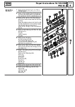
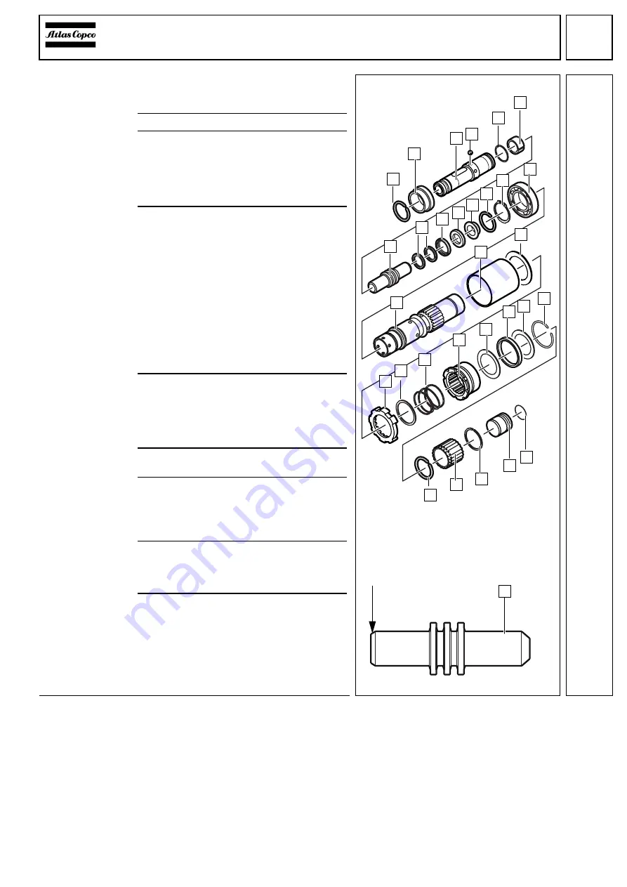
Assembling
the sleeve
1
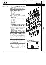
Press the ball bearing (E) onto the spindle
sleeve (F) and fit the locking ring (D) and
the O-ring (C).
2
Mount the ring (R) on the driver (S).
3
Mount the following parts on the
sleeve (M):
disc (N),
sleeve (O),
disc (P).
Insert the locking ring (Q).
4
Mount the following parts on the spindle
sleeve (F):
spring ring (K),
sleeve (G),
spring (L) (pressed over the toothing of the
spindle sleeve (F)),
washer (H),
sleeve (I),
sleeve (M),
driver (S).
☞
Mount the locking ring (T) on the spin-
dle sleeve (F) with aid of the cone
(service tool).
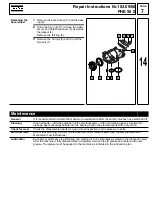
5
Mount the O-ring (V) on the striker (U) and
insert the striker (U) into the spindle
sleeve (F).
☞
The O-ring (V) must face the direction
of the four-lips-seal-ring of the piston.
6
Insert the ring (B), the rubber ring (A) and
the ring (9) into the spindle sleeve (F).
7
Fit the O-ring (5) on the drill spindle (3), in-
sert the distance sleeve (6) into the drill
spindle (3), and fit the seals (8) on the an-
vil (7).
Insert the anvil (7) into the drill spindle (3).
8
Insert the drill spindle (3) into the spindle
sleeve (F).
Insert the six balls (4) with aid of a magnet
into the drill spindle (3).
9
Mount the locking ring (1) and the retain-
ing ring (2) on the drill spindle (3).
☞
Mind the right position of the locking
ring (D) concerning the relieves in the
retaining ring (2).
2
1
6
5
4
7
9
B
C
A
D
8
F
H
G
O
N
M
L
K
I
S
V
U
T
3
P
R
E
Q
Anvil fitting position:
The shortened phase faces the drill
(to the front).
7
8
Summary of Contents for PHE 50 S
Page 1: ......


