12
PAGE
Repair Instructions No.178.06/97
PN 6000 S
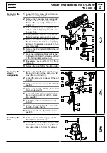
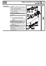
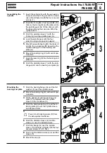
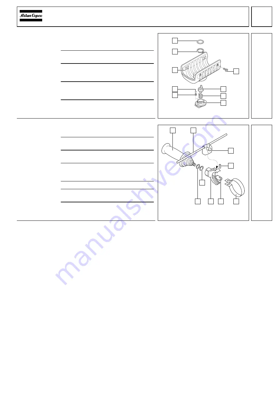
Mounting the
switch knob
1
Fit the torsion spring (8) to the shift pin (7)
such that it is located in the boring of the
shift pin (7).
2
Insert the shift pin (7) with the torsion
spring (8) into the gear box insulation (3).
3
Mount the ball (2), the pressure spring (1)
and the switch knob (9) from the outside in
the gear box insulation (3).
4
Insert the O-ring (5) into the gear box insu-
lation (3) and mount the locking ring (4)
with aid of special pliers.
5
Fit the gear box insulation (3) to the
machine and secure it with the four
screws (6).
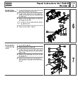
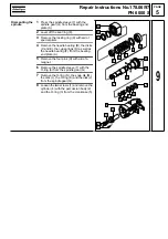
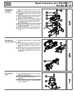
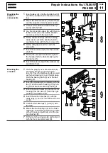
Mounting the
holding grip
1
Push the clamping plate (5) over the neck
of the machine.
2
Insert the nut (6) into the clamping
plate (5).
3
Push the pin (4) through the clamping
plate (5) and the nut (6).
4
Fit the plastic holder (7) to the machine
and secure it with the O-ring (8) and the
locking ring (9).
5
Screw down the holding grip (1).
6
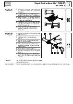
Push the holding device (3) over the depth
gauge (2).
7
Fit the depth gauge (2) with the holding
device (3) to the machine (see arrow in il-
lustration).
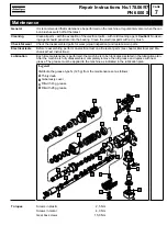
Test Run
Electrical Test
Test run the machine and pay attention to noises.
Let the machine run-in.
Perform an electrical test on the machine (see chapter Electrical and Mechanical Test Instructions).
1
6
5
4
3
2
7
8
9
10
1
6
5
4
3
2
7
8
9
11
Summary of Contents for PN 6000 S
Page 1: ......

