background image

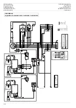
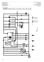
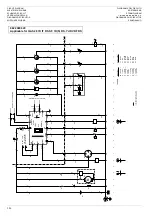
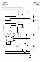
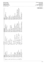
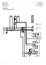
CIRCUIT DIAGRAM
ELEKTRISCH SCHEMA
SCHEMA DE CIRCUIT
VERDRAHTUNGSPLAN
DIAGRAMA DE CIRCUITOS
KOPPLINGSSCHEMA

DIAGRAMMA DEL CIRCUITO

KRETSSKJEMA

STRØMDIAGRAM

m€yl‹y‚‚y<°†‚yŒŠt

DIAGRAMMA DOS CIRCUÍTOS

SÄHKÖKAAVIO

381

DANS

K

}

o

o


ˆ

€

y

P

O

RTUGU

ÊS

SU

O

M

I

B

1

1

H

as

ti

gheds

føler

y

­·

¹¬

¸ 

¶¥

»

¸¥

¼¤

¸¬

¸¥

»

Sens

or

 de 

velo

ci

dade

Nopeus

an

tur

i

F1

-5

Sikr

ing 4A

y

·ª

‡°

©­

¥

y

Fus

ível 4A

Var

oke 4A

G3

Gene

ra

tor


l

©²

² 

¸¶

­¥

Ger

ador

Vai

h

tovi

rt

agener

aat

to

ri

K11

Hj

æ

lp

er

el

æ

 fo

r s

ndi

ngs

uds

ni

t (

ne

dr

e s

ndi

ng

)

|

³¬

¹¬

¸­¯


©´

­°

³«


¸‡

·¬

Ȧ

©°

Ÿ

¼¥

±¬

°¢

¸©

¶¬

¸‡

·¬

R

el

é au

xi

liar d

selecção

 d

e v

oltag

em 

(m

en

or

 v

oltag

em)

Ap

ur

eleen

 jän

nitteen

va

litsin

 (ma

talamp

i j

än

nite)

K12

H

lper

el

æ

 fo

r sp

æ

ndi

ng

sudsn

it (

øvr

e spæ

ndi

ng)

|

³¬

¹¬

¸­¯


©´

­°

³«


¸‡

·¬

Ȧ

©°

Ÿ

½…

¬°

¢¸

©¶

¬

¸‡

·¬

R

el

é au

xi

liar d

selecção

 d

e v

oltag

em 

(m

ai

or

 v

oltag

em)

Ap

ur

eleen

 jän

nitteen

va

litsin

 (k

or

ke

am

pi

 jän

nite)

N11

H

as

ti

gheds

re

gulator

}

°©

«¯

¸ 

»

¸¥

¼¤

¸¬

¸¥

»

C

o

ntr

o

la

d

o

da velo

ci

dade

Nopeuden 

valvoja

N12

A

utomati

sk s

p

æ

ndings

re

gul

at

or

y

½¸

¢±

¥¸

³»

½¹

±­

·¸

 »

¸

‡·

¬»

R

egu

lador

 automáti

co 

da potência

A

utomaatt

inen 

n

n

itteens

ää

d

in

N13

Jor

df

ejl

str

øms

relæ

¶©

¤±

¥¸

³»

«

©¡

º

·¬

»

R

el

é de de

te

cção de 

fa

lha 

de ter

ra

M

aavuo

tor

ele

P1

-3

Amper

em

et

er

 0-

500A

y

±´

©¶

¢±

©¸

¶³

y

Ampe

me

tro 0-

500A

Ampe

er

im

itta

ri

 0-

500 A

P4

Voltme

te

r 0-

500V

|

³°

¸¢

±©

¸¶

³

9

Voltím

et

ro 

0-50

0 V

V

oltti

mitta

ri

 0

-500 

V

P5

Fr

ekvens

måler

 45

-65Hz

‚

©¸

¶¬

¸ 

»

·½

¼²

¢¸

¬¸

¥»

+

]

Fr

equ

en

m

etr

o

 45-

65Hz

T

aajuus

mi

ttar

i 45-

65 

Hz

Q1.

1

Af

br

yder

m

­¥

¯¢

´¸

¬»

¯

½¯

°µ

±¥

¸³

»

Dis

juntor

Vir

rankatkais

in 

Q1.

2

Af

br

yder

m

­¥

¯¢

´¸

¬»

¯

½¯

°µ

±¥

¸³

»

Dis

juntor

Vir

rankatkais

in 

R

1

1

P

otenti

ometer

 til

 jus

ter

ing af

 f

ødes

p

æ

n

dingen

m

½²

¥±

¢±

©¸

¶³

¤¹

±­

·¬

»¸

‡·

¬»

´

¥¶

³¼

 »

P

o

tencióm

etr

o de 

aj

us

te da 

te

n

são de 

ali

m

entação

S

yött

ö

jännitt

ee

n s

ää

töpotenti

ometr

i

R

1

6

H

as

ti

gheds

ju

st

er

ing,

 k

un 60

 Hz

‹¤

¹±

­·

¬

¸¥

¼¤

¸¬

¸¥

»

+

]

±¢

²³

Ajus

te da 

velocidade,

 apenas

 60

 Hz 

ap

en

as

Nopeudens

ää

vain 

60 H

z

R

18

H

as

ti

gheds

af

vigels

e,

 kun 60 Hz

‚

©¸

¥¸

¢´

­·

¬

¸¥

¼¤

¸¬

¸¥

»

+

]

±¢

²³

R

egulação da var

iaç

ão

 da velo

cidade,

 ap

enas

 60 Hz

N

o

p

eu

sp

o

ik

k

ea

m

a,

 v

ai

n

 6

0

 H

z

S2

b

N

øds

top

³´

Ÿ

¯¸

¥¯

¸¬

»

¥²

‡«

¯¬

»

Par

agem de e

m

er

gência

Hätäpys

äy

tys

S4

Voltme

te

re

ts

 oms

k

if

te

rkn

ap 

m

­¥

¯¢

´¸

¬»

©

´­

°³

« 

»

¦³

°¸

³±

Ÿ¸

¶³

½

C

o

muta

dor

 s

ele

ct

or do voltí

me

tro

V

oltti

mitta

ri

n va

linta

kyt

kin

S1

0

O

ms

kif

te

rkontakt til

 udg

an

gs

sp

æ

nding

m

­¥

¯¢

´¸

¬»

©

´­

°³

« 

»

¸‡

·¬

»

©®

¢¨

³½

Inte

rr

upto

r s

ele

ct

or

 de

 volta

ge

m

 de

 s

aída

L

äh

nnitte

en

 va

linta

ky

tkin

S1

1

O

ms

kif

te

rkontakt 50Hz/6

0

Hz

m

­¥

¯¢

´¸

¬»

©

´­

°³

«©

¥

+

]

+

]

C

o

mutador

-s

elector

 50Hz/60Hz

V

alintakyt

kin 50Hz/60Hz

S1

3

A

fb

ryder

kont

ak

t t

il j

o

rd

fe

jls

tr

øm

sr

elæ

m

­¥

¯¢

´¸

¬»

¥

´³

¯°

©­

·±

³¤

±

©¸

‡¨

³·

¬»

°

‡¹

³½

»·

¸¬

«©

¡º

·¬

In

te

rr

upt

or

 s

el

ect

or

 do

 re

lé 

de 

cor

re

nt

e de

 de

fe

ito

 à 

te

rr

a

M

aavuo

don t

unnis

tim

en

 s

u

lkuky

tkin

T1

-3

S

tr

ømtr

an

sf

or

mer

e 500A

/5A

‚

©¸

¥·

¼¬

±¥

¸­

·¸

 »

©¤

±¥

¸³

»

y

y

T

ra

n

sf

or

mado

de cor

rente 5

00A/5A

V

ir

ta

m

uuntaja 

500A/5A

T

1

3

Jor

df

ejl

str

øms

d

etektor

y

²­

¼²

©½

¸ 

»

¶©

¤±

¥¸

³»

«

©¡

º

·¬

»

Detec

tor

 de f

alha de 

cor

re

n

te de 

ter

ra

M

aavuo

don t

unnis

tin

X1

Klembr

æ

d

t

q

¡²

¥¯

¥»

¥

¯¶

³¨

Ÿ¯

¸¬

Quadr

o

 de 

te

rm

in

ai

s

L

ii

nt

äl

evy

X25

K

le

mlis

te

o

º

¶¡

¨¥

¥

¯¶

³¨

Ÿ¯

¸¬

Fa

ixa

 de

 te

rmina

is

L

ii

ntä

rim

a

Y11

A

ktuator

}

²©

¶«

³´

³­

¬¸

 »

Ac

ci

ona

dor

T

o

imila

it

e

Sx

Konta

k

t til fj

er

ns

tyrin

g

 a

st

ar

t/

st

o

p

Œ

¬°

©¼

©­

¶­

¾¢

±©

²³

»

¨­

¥¯

¢´

¸¬

»

©¯

¯¡

²¬

·¬

»

¥²

¥¯

³´

 »

In

ter

rupto

r r

emoto

 de a

rr

anque/

p

ar

agem

Kaukokäynnis

tys

-/

kaukopys

äytys

kytki

n

Kx

M

as

k

inko

ntaktor

}

´¥

ªŸ

¥»

©

«¯

¥¸

‡·

¸¥

·¬

»

C

o

nta

ct

or ge

ra

l

L

ai

tt

ei

st

on 

liitin

1

L

ednin

g

sn

et

²¨

©·

±³

°³

«¡

¥

·½

¶±

‡¸

º

²

C

abl

agem ger

al

Joh

tos

ar

ja

9822 0888 26

Summary of Contents for QAS14 Yd(S)

Page 1: ...n 333 Circuit diagrams Elektrische schema s Sch mas de circuits Schaltpl ne Esquema de conexiones Kopplingsscheman Diagrammi dei circuiti Kretsskjema Kredsl bsdiagrammer m Y Esquemas el ctricos S hk k...

Page 2: ...QAS18 Yd S QAS18 YdS IT 2...

Page 3: ...QAS28 units 21 Circuit diagrams 21 Overview of the electrical options 21 Description of the electrical options 21 Overview of the mechanical options 28 Description of the mechanical options 28 Techni...

Page 4: ...ion failures All responsibility for any damage or injury resulting from neglecting these precautions or by non observance of ordinary caution and due care required in handling operating maintenance or...

Page 5: ...has to operate in a fire hazardous environment each engine exhaust has to be provided with a spark arrestor to trap incendiary sparks 2 The exhaust contains carbon monoxide which is a lethal gas When...

Page 6: ...g equipment On engine driven units the battery shall be disconnected and removed or the terminals covered by insulating caps On electrically driven units the main switch shall be locked in open positi...

Page 7: ...ich is fatal if it hits your eyes and which can cause burns if it contacts your skin Therefore be careful when handling batteries e g when checking the charge condition 2 Install a sign prohibiting fi...

Page 8: ...driven by a water cooled diesel engine manufactured by YANMAR An overview of the main parts is given in the diagram below DH 1 OLD OF C DFO ET FCO FCW AF E A F FPF DFW G1 FF QAS28 Yd S QAS28 YdS IT 1...

Page 9: ...IUM 1615 6945 00 Y A 3 606035 x x x x x x The QAS28 AC generator is available in 2 versions QAS28 Yd S and QAS28 YdS IT Some parts of the unit are different depending on which version QAS28 Yd S QAS28...

Page 10: ...d is energized Never use the guiding rods to lift the generator Indicates that an electric voltage dangerous to life is present Never touch the electric terminals during operation Indicates that the e...

Page 11: ...Lights up when the electrical system of the engine is energized L2 Engine preheating system indicator Lights up when the glow plugs in the engine used to facilitate starting are warming up Extinguish...

Page 12: ...ith the key to avoid unauthorized use Use this button only in case of an emergency Q1 Circuit breaker for X1 Interrupts the power supply X1 when a short circuit occurs at the load side or when the ove...

Page 13: ...ons Local rules concerning the setting up of low voltage power installations below 1 000 V must be respected when connecting site distribution panels switch gear or loads to the generator At each star...

Page 14: ...a power factor of 0 80 are respectively 6 mm2 and 120 m In case electric motors must be started oversizing the cable is advisable The voltage drop across a cable can be determined as follows e Voltage...

Page 15: ...ule goes out Push down the starter switch into position and release it as soon as the engine fires The switch automatically returns to position I Check that the warning lamps on the control and indica...

Page 16: ...are connected to the generator output ter minals keep all loads well balanced If circuit breakers are activated during operation switch off the load and stop the generator Check and if necessary decre...

Page 17: ...that combine all wear parts These service kits offer you the bene fits of genuine parts save on administration costs and are offered at reduced price compared to the loose components Refer to the par...

Page 18: ...ecessary after being recharged Submit the generator to a test run 6 1 7528 6 227 1 1 92 70 7 5 3 Put a voltmeter in parallel with voltmeter P4 on the control panel Check that the read out of both volt...

Page 19: ...and terminals of the electronic regulator a 12 V battery voltage with a 30 resistor in series respecting the polar ities After being excited alternator does not excite Connections are interrupted Che...

Page 20: ...e is too low Incorrect valve tip clearances Engine overload Blue or white exhaust smoke Wrong grade of lubricating oil Fault in cold start system Engine temperature is too low The engine knocks Fault...

Page 21: ...ual voltage DV dual voltage with switch DV SW single phase 1 PH 6 5 37 21 2 7 75 237 216 2XWOHW VRFNHWV 6 The Outlet sockets option provides the following extra outlet sockets and circuit breakers X2...

Page 22: ...it breaker Q1 Let the engine run for about 5 minutes Stop the engine by putting the starter switch in position O Lock the side doors and the door of the indicators and control panel to avoid unauthori...

Page 23: ...lable again for at least 10 sec onds mains restore time the following timing applies The generator contactor opens and the mains contactor closes 1 second change over time The generator shuts down 1 m...

Page 24: ...e AMF control module are L1 Mains available Lights up when the mains is available L2 Mains on load Lights up when the mains supplies power towards the load L3 Mains failed Lights up when a failure occ...

Page 25: ...to be installed by the customer The unit will start in case the contact is closed start stop switch in position start and the starter switch of the control module is in po sition position P3 6LQJOH IU...

Page 26: ...ers Q1 1 and Q1 2 cannot be switched on at the same time This is prevented by means of the auxiliary voltage selection relays K11 and K12 refer to the circuit diagram The selection of high or low volt...

Page 27: ...d by means of the auxiliary voltage selection relays K11 and K12 refer to the circuit diagram 6LQJOH SKDVH 3 The Single phase option provides single phase output voltage e g 230 V X1 Main power supply...

Page 28: ...using this option Make sure that the towing equipment of the vehicle matches the towing eye before towing the generator Never move the generator while electrical cables are connected to the unit Alway...

Page 29: ...ient temperature 40 C 40 C Maximum altitude 1000 m 1000 m Maximum relative air humidity 85 85 Minimum starting temperature 18 C 18 C Engine Type YANMAR 4TNE94 ACG 4TNE94 ACG Rated net output 20 kW 24...

Page 30: ...951 x 1157 mm 2080 x 951 x 1157 mm Weight net mass 859 kg 859 kg Weight wet mass 975 kg 975 kg QAS28 Yd S Setting of circuit breaker Q2 32 A 32 A QAS28 Yd S Setting of circuit breaker Q3 16 A 16 A QAS...

Page 31: ...n number 7 Model number 8 Frequency 9 Apparant power COP 10 Active power COP 11 Nominal rated voltage 12 Nominal rated current 13 Power factor 14 Manufacturing year 15 EEC mark in accordance witt Mach...

Page 32: ...QAS28 Yd S QAS28 YdS IT 32...

Page 33: ...363 Circuit diagrams Elektrisch schema Sch ma de circuit Schaltpl ne Esquema de conexiones Kopplingsscheman Diagrammi dei circuiti Kretsskjema Kredsl bsdiagrammer m Y Esquemas el ctricos S hk kaaviot...

Page 34: ...ENERATOR TERMINALS X25 X3 L1 X3 L2 X3 L3 X3 X3 1 2 3 4 5 6 7 8 5 a0 X25 5 7 a0 X25 7 8 a6 X25 for use with Wire section N l1 L3 earth QAS 14 38 16 mm 16 mm QAS 48 78 50 mm 25 mm QAS 108 138 70 mm 35 m...

Page 35: ...PA OL SVENSKA ITALIANO NORSK F1 4 Fusible 6A S kring 6A Fusibile 6A Sikring 6A MC Suministro principal del contactor N tstr msanslutning Alimentazione contattore Kontaktorstr mforsyning PC D namo del...

Page 36: ...Diagram Interconnection Generator Mains Supply PC A1 A2 MC Fx A1 A2 REMOTE START MAINS SUPPLY 3 phase N PE L3 L2 L1 N PE N13 U1 9 10 TEST AUTO PL PN PC MC ML3 ML2 ML1 MN X25 X16 X15 X15 X15 X15 X16 X2...

Page 37: ...g nur 60 Hz R18 Speed offset 60 Hz only Snelheidsoffset enkel 60 Hz D calage de vitesse 60 Hz uniquement Drehzahlausgleich nur 60 Hz S2b Emergency stop Noodstopknop Arr t d urgence Notabschaltung S4 V...

Page 38: ...Diagram Interconnection Generator Mains Supply PC A1 A2 MC Fx A1 A2 REMOTE START MAINS SUPPLY 3 phase N PE L3 L2 L1 N PE N13 U1 9 10 TEST AUTO PL PN PC MC ML3 ML2 ML1 MN X25 X16 X15 X15 X15 X15 X16 X2...

Page 39: ...Compensaci n de velocidad s lo 60 Hz Hastighetens grundinst llning endast 60 Hz Sfalsatura velocit solo 60 Hz Hastighetsforskyvning bare 60 Hz S2b Parada de emergencia N dstopp Arresto di emergenza N...

Page 40: ...Diagram Interconnection Generator Mains Supply PC A1 A2 MC Fx A1 A2 REMOTE START MAINS SUPPLY 3 phase N PE L3 L2 L1 N PE N13 U1 9 10 TEST AUTO PL PN PC MC ML3 ML2 ML1 MN X25 X16 X15 X15 X15 X15 X16 X2...

Page 41: ...juste da velocidade apenas 60 Hz apenas Nopeudens t vain 60 Hz R18 Hastighedsafvigelse kun 60 Hz Regula o da varia o da velocidade apenas 60 Hz Nopeuspoikkeama vain 60 Hz S2b N dstop t Paragem de emer...

Page 42: ...REMOTE START MAINS SUPPLY 3 phase N PE L3 L2 L1 N PE U1 9 10 TEST AUTO PL PN PC MC ML3 ML2 ML1 MN X25 X16 X15 X15 X15 X15 X16 X25 a3 a3 448 449 Customer s install Sx min 12V dc 4A 0 Sx S14 13 14 Q1 X1...

Page 43: ...annung R16 Speed adjust 60 Hz only Snelheidsregeling enkel 60 Hz R gulation de vitesse 60 Hz uniquement Drehzahleinstellung nur 60 Hz R18 Speed offset 60 Hz only Snelheidsoffset enkel 60 Hz D calage d...

Page 44: ...REMOTE START MAINS SUPPLY 3 phase N PE L3 L2 L1 N PE U1 9 10 TEST AUTO PL PN PC MC ML3 ML2 ML1 MN X25 X16 X15 X15 X15 X15 X16 X25 a3 a3 448 449 Customer s install Sx min 12V dc 4A 0 Sx S14 13 14 Q1 X1...

Page 45: ...60 Hz Hastighetsjustering endast 60 Hz Regolazione della velocit solo 60 Hz Hastighetsjustering bare 60 Hz R18 Compensaci n de velocidad s lo 60 Hz Hastighetens grundinst llning endast 60 Hz Sfalsatu...

Page 46: ...REMOTE START MAINS SUPPLY 3 phase N PE L3 L2 L1 N PE U1 9 10 TEST AUTO PL PN PC MC ML3 ML2 ML1 MN X25 X16 X15 X15 X15 X15 X16 X25 a3 a3 448 449 Customer s install Sx min 12V dc 4A 0 Sx S14 13 14 Q1 X1...

Page 47: ...i metro de ajuste da tens o de alimenta o Sy tt j nnitteen s t potentiometri R16 Hastighedsjustering kun 60 Hz Ajuste da velocidade apenas 60 Hz apenas Nopeudens t vain 60 Hz R18 Hastighedsafvigelse k...

Page 48: ...S13 K12 S11 L1 L2 L3 N PE QAS 28 QAS 38 63A 80A 0_1000A 0_1000A g h Q1 1 40A 50A Q1 2 P1 Wire size X f f Y g g Z n R16 1K 3K3 R18 b54 b54 see note 2 237 238 R11 1 1 1 1 B11 233 234 N11 ACT MPU 233 234...

Page 49: ...e Schalter Fernstart stop Kx Plant contactor Installatiecontactor Contacteur d installation Anlagenseitiges Sch tz 1 Wire Harness Kabelbundel Harnais de c bles Kabelbaum ESPA OL SVENSKA ITALIANO NORSK...

Page 50: ...S13 K12 S11 L1 L2 L3 N PE QAS 28 QAS 38 63A 80A 0_1000A 0_1000A g h Q1 1 40A 50A Q1 2 P1 Wire size X f f Y g g Z n R16 1K 3K3 R18 b54 b54 see note 2 237 238 R11 1 1 1 1 B11 233 234 N11 ACT MPU 233 234...

Page 51: ...tor Virrankatkaisin R11 Potentiometer til justering af f desp ndingen m Potenci metro de ajuste da tens o de alimenta o Sy tt j nnitteen s t potentiometri R16 Hastighedsjustering kun 60 Hz Ajuste da v...

Page 52: ...grey 9 white 0 black e2 b3 b3 b3 b3 b3 b3 c3 a3 a3 a3 2 2 7 6 6 4 4 7 9 9 5 5 3 3 87 30 1 1 c2 c2 X10 S2 F4 X16 10A X16 X16 X16 X16 X16 X16 11 5 7 4 3 9 2 1 6 H1 X16 X10 X10 X10 12 12 X10 X10 X10 X10...

Page 53: ...stop solenoid Brandstofstopsoleno de Sol no de d arr t de carburant Kraftstoffabsperrmagnet ESPA OL SVENSKA ITALIANO NORSK B7 Sensor del nivel de combustible Sensor br nsleniv Sensore del livello di...

Page 54: ...grey 9 white 0 black e2 b3 b3 b3 b3 b3 b3 c3 a3 a3 a3 2 2 7 6 6 4 4 7 9 9 5 5 3 3 87 30 1 1 c2 c2 X10 S2 F4 X16 10A X16 X16 X16 X16 X16 X16 11 5 7 4 3 9 2 1 6 H1 X16 X10 X10 X10 12 12 X10 X10 X10 X10...

Page 55: ...Kontrolmodul t M dulo de controlo Ohjainmoduli P6 Timet ller Contador de horas K ytt tuntimittari P7 Br ndstofniveaumeter Indicador do n vel de combust vel Polttoainemittari P8 Indicador de temperatur...

Page 56: ...2 7 6 6 4 4 7 9 9 5 5 3 3 1 1 c2 c2 X10 S2 F4 X16 10A X16 X16 X25 1 X25 2 to Power Circuit Diagram X16 X16 X16 X16 X16 11 5 7 4 3 9 2 1 REMOTE START REMOTE OFF TEST 06 6 21 22 PC H1 X16 X10 X10 X10 12...

Page 57: ...op solenoid Brandstofstopsoleno de Sol no de d arr t de carburant Kraftstoffabsperrmagnet ESPA OL SVENSKA ITALIANO NORSK B7 Sensor del nivel de combustible Sensor br nsleniv Sensore del livello di com...

Page 58: ...2 7 6 6 4 4 7 9 9 5 5 3 3 1 1 c2 c2 X10 S2 F4 X16 10A X16 X16 X25 1 X25 2 to Power Circuit Diagram X16 X16 X16 X16 X16 11 5 7 4 3 9 2 1 REMOTE START REMOTE OFF TEST 06 6 21 22 PC H1 X16 X10 X10 X10 12...

Page 59: ...olo Ohjainmoduli P6 Timet ller Contador de horas K ytt tuntimittari P7 Br ndstofniveaumeter Indicador do n vel de combust vel Polttoainemittari P8 K levandstermometer Indicador da temperatura do refri...

Page 60: ...e size aa 0 5 mm 2 a 1 mm 2 b 1 5 mm 2 c 2 5 mm 2 d 4 mm 2 e 6 mm 2 f 10 mm 2 g 16 mm 2 h 25 mm 2 i 35 mm 2 j 50 mm 2 Colour code 1 brown 2 red 3 orange 4 yellow 5 green 6 blue 7 purple 8 grey 9 white...

Page 61: ...op solenoid Brandstofstopsoleno de Sol no de d arr t de carburant Kraftstoffabsperrmagnet ESPA OL SVENSKA ITALIANO NORSK B7 Sensor del nivel de combustible Sensor br nsleniv Sensore del livello di com...

Page 62: ...e size aa 0 5 mm 2 a 1 mm 2 b 1 5 mm 2 c 2 5 mm 2 d 4 mm 2 e 6 mm 2 f 10 mm 2 g 16 mm 2 h 25 mm 2 i 35 mm 2 j 50 mm 2 Colour code 1 brown 2 red 3 orange 4 yellow 5 green 6 blue 7 purple 8 grey 9 white...

Page 63: ...olo Ohjainmoduli P6 Timet ller Contador de horas K ytt tuntimittari P7 Br ndstofniveaumeter Indicador do n vel de combust vel Polttoainemittari P8 K levandstermometer Indicador da temperatura do refri...

Page 64: ...3 4 X25 X25 X25 X25 a3 a3 a0 a0 330 331 332 333 from Remote Start module see Engine Circuit Diagram Customer s installation Sx min 12V dc 4A Kx to be wired between Generator and Load coil max 240VAC 3...

Page 65: ...r Interrupteur de d marrage arr t distance Schalter Fernstart stop Kx Plant contactor Installatiecontactor Contacteur d installation Anlagenseitiges Sch tz ESPA OL SVENSKA ITALIANO NORSK F1 3 Fusible...

Page 66: ...3 4 X25 X25 X25 X25 a3 a3 a0 a0 330 331 332 333 from Remote Start module see Engine Circuit Diagram Customer s installation Sx min 12V dc 4A Kx to be wired between Generator and Load coil max 240VAC...

Page 67: ...Aquecedor do l quido de arrefecimento do motor Moottorin j hdytysnesteen l mmitysvastus S2b N dstop t Paragem de emerg ncia H t pys ytys S4 Voltmeterets omskifterknap m Comutador selector do volt met...

Page 68: ...UIT DIAGRAM ELEKTRISCH SCHEMA SCHEMA DE CIRCUIT VERDRAHTUNGSPLAN DIAGRAMA DE CIRCUITOS KOPPLINGSSCHEMA DIAGRAMMA DEL CIRCUITO KRETSSKJEMA STR MDIAGRAM m yl y y y t DIAGRAMMA DOS CIRCU TOS S HK KAAVIO...

Reviews: