2.5
Electric diagram
• The electrical installation must correspond to the applicable codes.
• The mains supply and earthing lines must be of suitable size. See section
Electric
cable size and fuses
.
• The installation must be earthed and protected by fuses in each phase.
• An isolating switch must be installed near the compressor. Make sure that this
switch is open to isolate the compressor from the mains before carrying out any
connection.
The complete electrical diagram is available in the electric cubicle of the compressor. For
connection of the supply wires, please see section
Electrical connections
.
2.6
Temperature protection
The compressor is equipped with an ambient temperature sensor. The sensor creates a warning
message on the controller if the ambient temperature rises above 40 °C (104 °F). If the ambient
temperature reaches 45 °C (113 °F), the compressor is stopped.
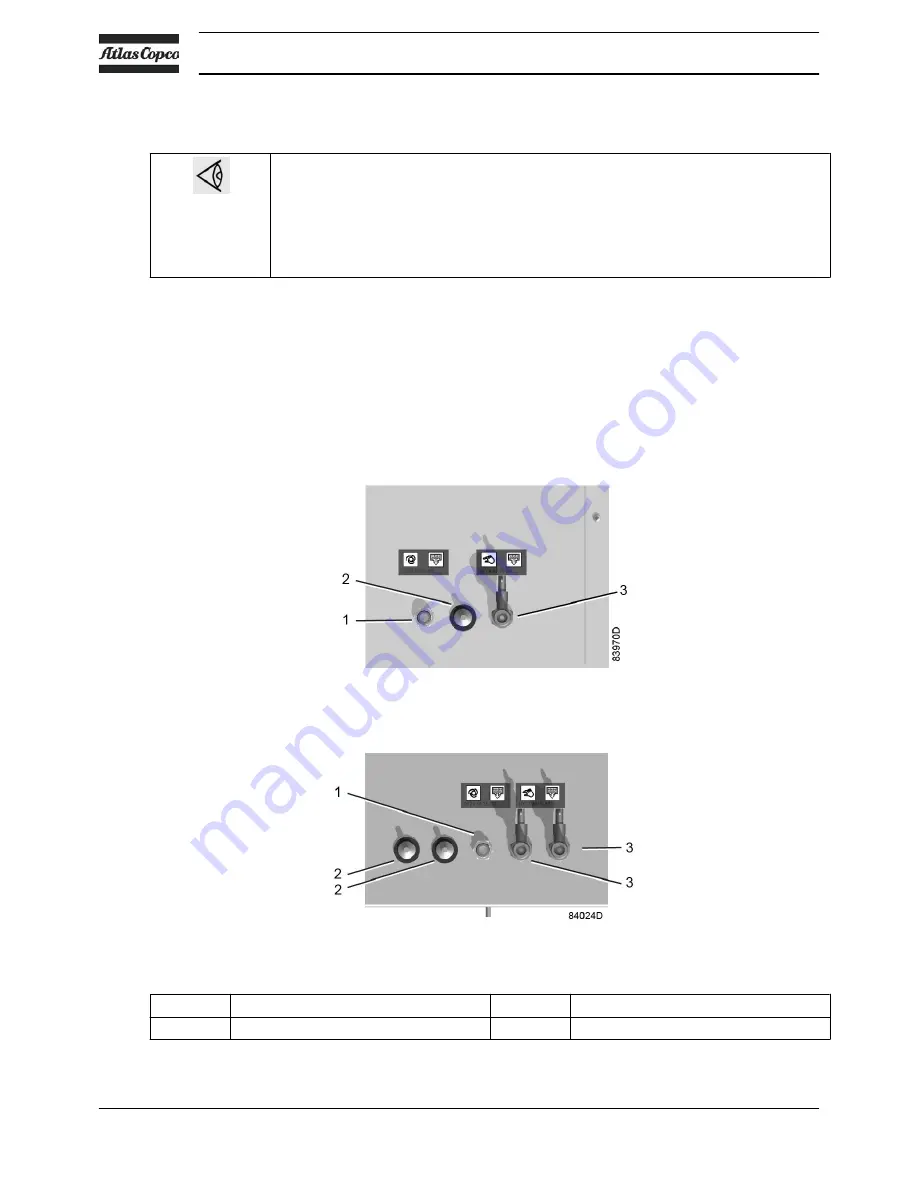
Condensate drain connections
Condensate drain connections on SFD
1
Automatic condensate drain outlet
3
Manual condensate drain valve
2
Ambient temperature sensor
Instruction book
20
2920 7140 52
Summary of Contents for SF 15+
Page 1: ...INSTRUCTION BOOK OIL FREE SCROLL COMPRESSORS SF 15 SF 17 SF 22 SFD 11 SFD 15 SFD 22 ...
Page 2: ......
Page 16: ...2 2 Flow diagram Flow diagram of SF 15 SF 17 SF 22 Instruction book 14 2920 7140 52 ...
Page 18: ...Flow diagram of SFD 11 SFD 15 SFD 22 Instruction book 16 2920 7140 52 ...
Page 112: ......
Page 113: ......


