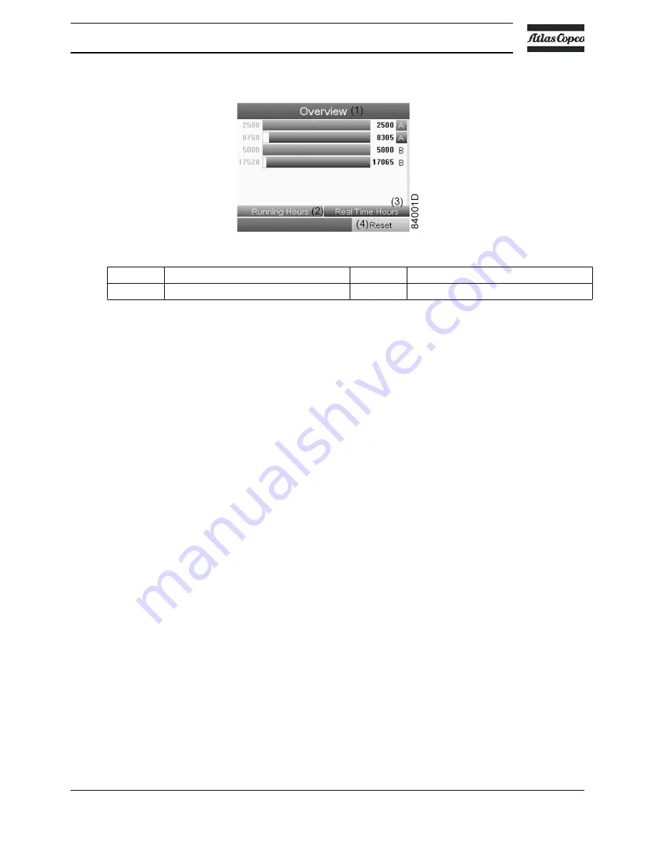
Overview
Text on image
(1)
Overview
(3)
Real Time (hours)
(2)
Running Hours
(4)
Reset
Example for service level (A):
The figures at the left are the programmed service intervals. For Service interval A, the
programmed number of running hours is 2500 hours (upper row) and the programmed number of
real time hours is 8760 hours, which corresponds to one year (second row). This means that the
controller will launch a service warning when either 2500 running hours or 8760 real hours are
reached, whichever comes first. Note that the real time hours counter keeps counting, also when
the controller is not powered.
A new algorithm is implemented for a better protection of the compressor elements. The running
hours will be recalculated depending on the ambient temperature. A compressor continuously
running in an ambient temperature between 30 °C (86 °F) and 35 °C (95 °F) is working in harder
conditions than an element running at 20 °C (68 °F). Therefore a service done earlier (a time
reduction of 30 % is applied in this temperature zone) will protect the element in a better way. In
the zone between 35 °C (95 °F) and 40 °C (104 °F), the time reduction is 60 %.
The figures within the bars are the number of hours to go till the next service intervention. In the
example above, the compressor was just started up, which means it still has 2500 running hours
or 8305 hours to go before the next Service intervention.
Service plans
A number of service operations are grouped (called Level A, Level B, etc...). Each level stands
for a number of service actions to be carried out at the time intervals programmed in the
controller.
When a service plan interval is reached, a message will appear on the screen.
After carrying out the service actions related to the indicated levels, the timers must be reset.
From the Service menu above, select Service plan (3) and press Enter. Following screen
appears:
Instruction book
2920 7140 52
47
Summary of Contents for SF 15+
Page 1: ...INSTRUCTION BOOK OIL FREE SCROLL COMPRESSORS SF 15 SF 17 SF 22 SFD 11 SFD 15 SFD 22 ...
Page 2: ......
Page 16: ...2 2 Flow diagram Flow diagram of SF 15 SF 17 SF 22 Instruction book 14 2920 7140 52 ...
Page 18: ...Flow diagram of SFD 11 SFD 15 SFD 22 Instruction book 16 2920 7140 52 ...
Page 112: ......
Page 113: ......


