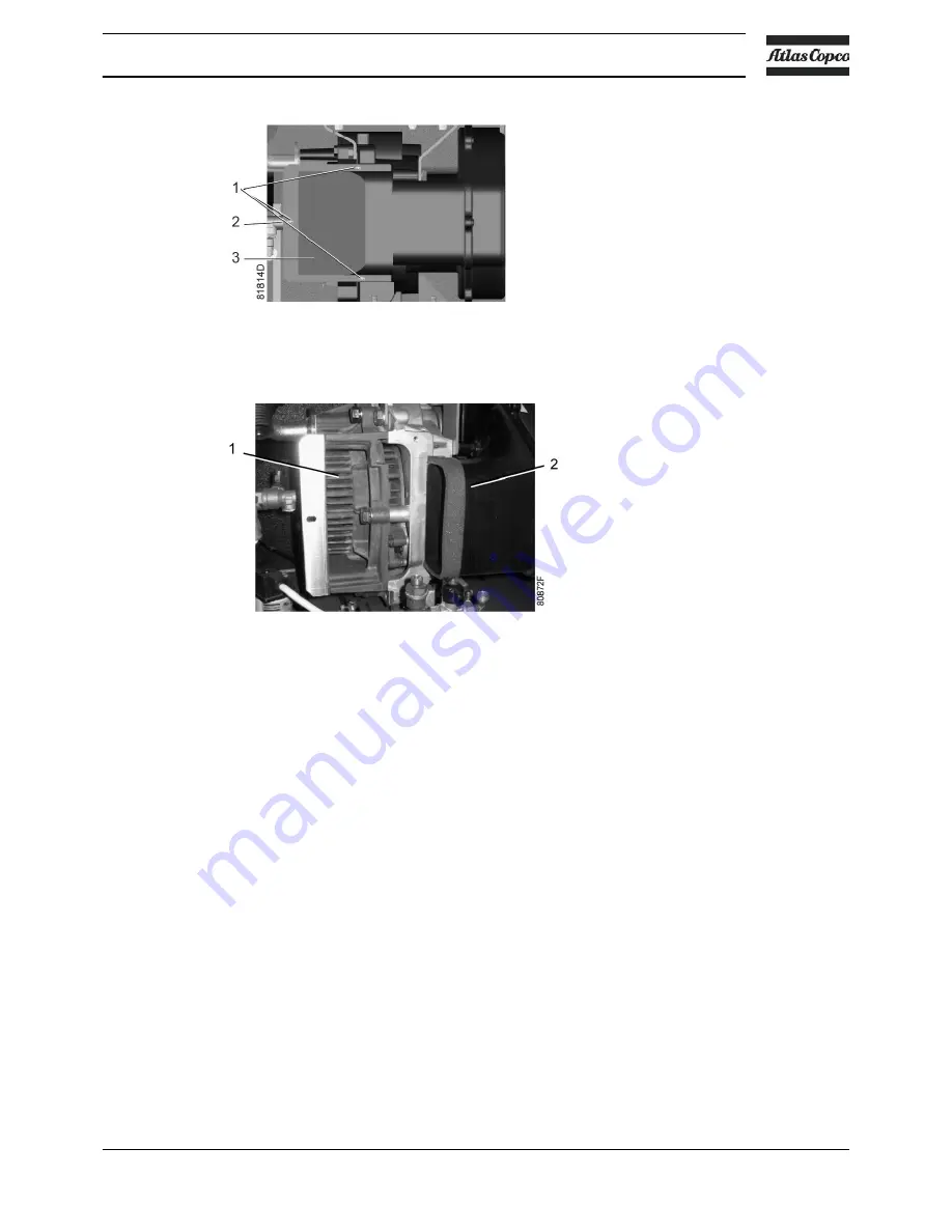
• Remove fan duct (3).
4. Clean cooling channels:
• Remove dust from the cooling channels (1) by means of air jet (see next figure).
• Clean the fan duct (2).
5. Reassemble the fan duct:
• Put the fan duct in place.
• Fit the 3 bolts and the clip.
The unit is now again ready for use.
7.7
Replacement of the outlet pipe
(only applicable to SF 15+ and SFD 15+)
From S/N API 772 000 onwards, a new type of 3.7 kW compressor element is used on the SF 15
+
and the SFD 15
+
. This
new element does no longer have a plastic insert in the outlet pipe and replacement is no longer required.
Description
The element outlet pipe (1) of the 3.7 kW element contains a plastic insert (3). Due to the heat of
the compressed air, the plastic insert can become brittle after time. Therefore it is recommended
to replace the outlet pipe together with the insert when that is the case. Both parts are available
as a kit (outlet pipe set). See the Spare Parts List for part number.
The outlet pipe set contains two parts:
• The plastic insert (3)
• The metal outlet pipe (1)
Instruction book
2920 7140 52
91
Summary of Contents for SF 15+
Page 1: ...INSTRUCTION BOOK OIL FREE SCROLL COMPRESSORS SF 15 SF 17 SF 22 SFD 11 SFD 15 SFD 22 ...
Page 2: ......
Page 16: ...2 2 Flow diagram Flow diagram of SF 15 SF 17 SF 22 Instruction book 14 2920 7140 52 ...
Page 18: ...Flow diagram of SFD 11 SFD 15 SFD 22 Instruction book 16 2920 7140 52 ...
Page 112: ......
Page 113: ......


