background image

XAHS365 Md

16

N

OTES

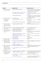
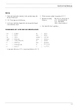
1. Top up with fuel at the end of each day's operation to prevent

condensate from contaminating the fuel.

2. More frequently when operating in high ambient temperatures.

3. More frequently when operating in a dusty atmosphere.

4. Screw the cap of the safety valve anticlockwise using a glove.

After testing, retighten the cap by hand.

5. Use ball bearing grease for the wheel bearings, graphite grease

for the drawbar and spindle.

6. Drain until clean fuel flows from the drain cock.

7. Some oil brands launch special oil types for screw compressors

allowing a longer oil change interval. Consult Atlas Copco.

8. Use Atlas Copco oil filters, with by-pass valve, as specified in

the parts list.

9. Replace the fuel filters regularly. Gummed or clogged filters

mean fuel starvation and reduced engine performance. The
quality of the fuel determines the frequency of filter renewal.

10. Replace the element if pressure drop exceeds 0.8 bar (12 psi).

11. To be performed only initially, after the first 50 hours.

B

ATTERY


CARE

Charging

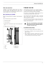
Before handling batteries, read the chapter ‘Safety precautions’ and
act accordingly. A Service Bulletin (ASB) dealing elaborately with
batteries and due care is available on request.

Maintenance

Keep the batteries clean and dry, the electrolyte level at 10 to 15
mm  (0.4 to 0.6 inch) above the plates or at the indicated level. Top
up with distilled water only. Cover the terminals lightly with
petroleum jelly.

S

TORAGE

Regularly run the compressor until it is warmed up. Load and
unload the compressor a few times. Keep the outlet valve closed
after stopping.

If the compressor is going to be stored without running from time
to time, protective measures must be taken as described in a
separate Service Bulletin (ASB), which may be obtained on
request.

S

ERVICE


PAK

The service paks of Atlas Copco offer you all the benefits of
genuine Atlas Copco parts. Service programmes and paks provide
for the right parts and maintenance for your compressor and engine.
The use of service paks minimises downtime and keeps your
maintenance budget low. The order numbers of the service paks
kits are listed on top of the maintenance schedule.

Contact your Atlas Copco representative for more information.

Summary of Contents for XAHS365 Md

Page 1: ...VISION www atlascopco com Instruction Manual for Portable Compressors XAHS365 Md Instruction manual for portable compressors 3 Circuit diagrams 339 Registration code Collection APC XII Tab 38 Printed Matter N 2927 1233 03 10 2000 ...

Page 2: ...XAHS365 Md 2 ...

Page 3: ...lchocks 25 Safety chain 25 Cold start 25 Electric fuel pump 25 Towbar level device for wagon 25 Pneumatic brakes and road signalisation for wagon and tandem 25 Axles and adjustable towbar for tandem with pneumatic brakes 26 Aftercooler waterseparator and fine filter 26 Aftercooler water and oilseparator fine filter and reheater 26 Technical specifications 27 Readings on gauges 27 Torque values 27 ...

Page 4: ...he environment due to leakage of oil solvents or other substances endanger the machinery due to function failures All responsibility for any damage or injury resulting from neglecting these precautions or by non observance of ordinary caution and due care required in handling operating maintenance or repair also if not expressly mentioned in this instruction manual is disclaimed by Atlas Copco The...

Page 5: ...n machine cooling fan this may cause overheating of the unit if taken in for combustion the engine power will be reduced SAFETY DURING USE AND OPERATION 1 When the unit has to operate in a fire hazardous environment each engine exhaust has to be provided with a spark arrestor to trap incendiary sparks 2 The exhaust contains carbon monoxide which is a lethal gas When the unit is used in a confined ...

Page 6: ...elow or in excess of its limits as indicated in the technical specifications SAFETY DURING MAINTENANCE AND REPAIR Maintenance overhaul and repair work shall only be carried out by adequately trained personnel if required under supervision of someone qualified for the job 1 Use only the correct tools for maintenance and repair work and only tools which are in good condition 2 Parts shall only be re...

Page 7: ...condition 2 Install a sign prohibiting fire open flame and smoking at the post where batteries are being charged 3 When batteries are being charged an explosive gas mixture forms in the cells and might escape through the vent holes in the plugs Thus an explosive atmosphere may form around the battery if ventilation is poor and can remain in and around the battery for several hours after it has bee...

Page 8: ... normal effective working pressure of 12 bar 175 psi The compressor is driven by a liquid cooled diesel engine manufactured by MERCEDES An overview of the main parts is given in the diagram below General descr XAHS365 T AV RV SV OF AR OS OFP MPV H22 1 DS E 5 OFe SR FC3 3 AF C FP FC1 FF2 4 B FF1 FT SG FC2 2 F EB 80 10 0 0 20 40 60 TG ...

Page 9: ...Oil filters compressor OFe Oil filter engine OFP Oil filler plug compressor RV Regulating valve SG Sight glass SR Speed regulator engine SV Safety valve T Towbar TG Temperature gauge BODYWORK The compressor the engine the cooling system etc are enclosed in a sound insulated bodywork that can be opened by means of side front and rear service doors A lifting eye is provided under a small door on top...

Page 10: ...ce repair or replacement of any device or element of design incorporated into any new compressor for the purpose of noise control prior to its sale or delivery to the ultimate purchaser or while it is in use 2 The use of the compressor after such device or element of design has been removed or rendered inoperative by any person Among those acts included in the prohibition against tampering are the...

Page 11: ...hing if coolant temperature is too high H8 Engine oil pressure fault indicator lamp Starts flashing if the engine oil pressure is too low H9 Compressor temperature fault indicator lamp Starts flashing if the compressor element outlet temperature is too high H10 Engine coolant level fault indicator lamp Starts flashing if the coolant level is too low H11 Fuel level fault indicator lamp Lights up if...

Page 12: ...pressor element compartment Normal closed switch Opens if the air outlet temperature exceeds the setting of the switch S14 Engine coolant temperature shutdown switch Located on the water manifold on top of the cylinder head Normal open switch Closes if temperature rises above the setting of the switch S37 1 Low fuel level shutdown switch Located in the fuel tank Normal open switch Closes if the fu...

Page 13: ... DP1 Drain plug oil cooler DP2 Drain plug air receiver DP3 Drain plug check valve DP4 Drain plug oil stop valve E Engine F Fan FR Flow restrictor oil scavenging line MPV Minimum pressure valve with none return valve OC Oil cooler OF Oil filter OFP Oil filler plug OSE Oil separator element OSV Oil stop valve RV Regulating valve SG Sight glass SR Speed regulator SV Safety valve S10 Pressure switch a...

Page 14: ...START button and hold until the engine fires The alternator charging indication lamp and the engine oil pressure lamp will extinguish when the alternator supplies power and the oil pressure has built up Notes 1 The start prevention switch S18 prevents the engine from starting as long as the pressure in the vessel exceeds 1 6 bar 2 To restart push the ON OFF button first LOADING 1 To select automat...

Page 15: ...eck Clean Check Clean Check Clean Electrolyte and terminals of batteries Check Check Check Tension and condition of belts Check Check Check Routing and condition of flexible hoses Check Check Check Oil water fuel system Check for leaks Check for leaks Check for leaks Flexible joints and pivots of engine stop solenoid Lubricate Lubricate Lubricate Flexible joints and pivots of speed regulator Lubri...

Page 16: ...urs BATTERY CARE Charging Before handling batteries read the chapter Safety precautions and act accordingly A Service Bulletin ASB dealing elaborately with batteries and due care is available on request Maintenance Keep the batteries clean and dry the electrolyte level at 10 to 15 mm 0 4 to 0 6 inch above the plates or at the indicated level Top up with distilled water only Cover the terminals lig...

Page 17: ...seats on the manifold taking care that no dirt drops into the system Oil the gaskets of the new oil filters Screw the filters into place until the gaskets contact their seats then tighten one half turn only 4 Drain the oil by removing all these drain plugs the air receiver oil separator oil cooler oil stop valve check valve and gearbox drain plug Reinstall and tighten the plugs using new gaskets a...

Page 18: ...er use a wire brush or metal objects Then clean by air jet in reverse direction of normal flow If the dirt is oily wash the coolers with fuel or a cleaning agent A spray gun should preferably be used to apply the solvent to the fins Rinse the block by means of a water jet after a soak in period Steam cleaning may also be applied Close the service doors Do not leave liquids behind SAFETY VALVE Foll...

Page 19: ... The coolant is a mixture of water and anticorrosion antifreeze agent The coolant must remain in the system all the year round to ensure adequate corrosion protection and to increase the boiling point Renew the coolant every two years as the corrosion protection diminishes It is not permitted to use water alone as a coolant even if antifreeze properties are not required The water in the coolant ha...

Page 20: ...with its coupling from the air intake chamber 2 Fit the switch to a tee Connect a vacuum gauge and a hose or pipe to the tee 3 Reconnect the wires to the switch and press the on off push button 4 Create a vacuum with the mouth through the hose while observing the vacuum gauge and the filter servicing alarm lamp The lamp should light up when the vacuum has reached the setting of the switch Replace ...

Page 21: ...ch only one restarting attempt is permitted while tracing the fault Always check the alarm lamps during starting as the lamps indicate which switch has tripped thus assisting in tracing the trouble Any bulb can be replaced An electrical fault must be traced by an electrician Make sure that the wires are not chafed damaged or broken and that they are clamped tight to their terminals ALTERNATOR PREC...

Page 22: ...b Insufficient engine oil pressure b Stop at once consult Operating Instructions book of the engine c Engine oil pressure switch S5 or compressor temperature switch S7 defective c Stop at once test switches replace as necessary d Engine temperature switch S14 or fuel level sensor B6 defective d Stop at once Test switches replace as necessary e Low coolant level e Fill coolant tank 6 Hourmeter P3 d...

Page 23: ...rewing the long ones g Safety valve leaking g Remove and inspect Replace if not airtight after reinstallation h Bleed off valve leaking h Remove and inspect Replace if necessary 12 Pressure in air receiver rises above maximum and causes safety valve to blow a Regulating valve opens too late or its ball valve spring is broken a Dismantle and inspect parts b Air leaks in regulating system b Check ho...

Page 24: ...ooling a Locate compressor away from walls when banked with other compressors leave space between them b Oil cooler clogged externally b Clean oil cooler c Oil cooler clogged internally c Consult Atlas Copco d Oil filters clogged d Replace filters e Oil level too low e Check oil level Top up level if necessary f Thermostatic by pass valve remains stuck in open position f Remove and check for prope...

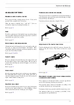
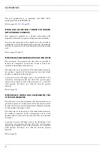
Page 25: ...tion heater warms up the cooling water that is circulated through the engine Thereby the water will warm up the engine which will make starting easier Refer to page 454 ELECTRIC FUEL PUMP The electric fuel pump option makes it easier to pump fuel from the fuel tank to the engine without use of the handpump Always make sure the filter in the fuel suction pipe is not clogged Refer to page 398 TOWBAR...

Page 26: ...nated by the fine filter A pressure decrease will appear due to the installation of the aftercooler waterseparator and fine filter The pressure gauge indicates the pressure in front of the aftercooler As a result the outlet pressure will always be a little less than the pressure indicated Refer to page 450 AFTERCOOLER WATER AND OILSEPARATOR FINE FILTER AND REHEATER The aftercooler water and oilsep...

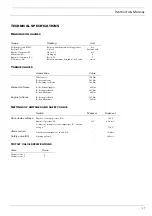
Page 27: ...eed r min Assemblies Value Wheel nuts 1 200 Nm Bolts frame axles 205 Nm Bolts lifting eye frame 205 Nm Element to frame Bolts element support 80 Nm Bolts support buffer 205 Nm Bolts buffer frame 80 Nm Engine to frame Bolts support buffer 205 Nm Bolts buffer frame 80 Nm Switch Makes at Brakes at Shut down switches Engine coolant temperature S14 105 C Engine oil pressure S5 1 14 0 8 bar e Compressor...

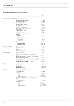
Page 28: ...oil system 66 l Engine oil system 15 l Fuel tank 334 l Engine cooling system 54 l Compressor Air receiver capacity 192 l Temperature above ambient of air leaving air outlet valves 60 C Max ambient temperature at sea level normal working pressure and max load speed 50 C Sound power level LW complies with 84 532 533 EEC and 85 406 EEC limits 102 dB A Sound pressure level according to ISO 2151 74 dB ...

Page 29: ...SO 1217 ed 3 1996 annex D Tolerance 5 25l s FAD 250l s 4 250l s FAD FAD Free air delivery 6 If not limited by local regulations CONVERSION LIST OF SI UNITS INTO BRITISH UNITS A temperature difference of 1 C a temperature difference of 1 8 F 1 bar 14 504 psi 1 m 3 281 ft 1 g 0 035 oz 1 mm 0 039 in 1 kg 2 205 lb 1 m3 min 35 315 cfm 1 km h 0 621 mile h 1 mbar 0 401 in wc 1 kW 1 341 hp UK and US 1 N 0...

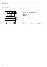
Page 30: ...xle C Maximum permitted road weight of the rear axle 1 Company code 2 Product code 3 Unit serial number 4 Name of manufacturer 5 EEC or national type approval number 6 Vehicle identification number 7 Working pressure 8 Speed 9 Engine power 10 Manufacturing year 11 EEC mark in accordance with Machine Directive 89 392 EEC ...

Page 31: ... diagrams Elektrische schema s Schémas de circuits Schaltpläne Esquema de conexiones Kopplingsscheman Diagrammi dei circuiti Kretsskjema Kredsløbsdiagrammer ÄιαγρÜììατα κυκλωìÜτωv Esquemas eléctricos Sähkökaaviot ...

Page 32: ...RISCH SCHEMA SCHEMA DE CIRCUIT VERDRAHTUNGSPLAN DIAGRAMA DE CIRCUITOS KOPPLINGSSCHEMA DIAGRAMMA DEL CIRCUITO KRETSSKJEMA STRØMDIAGRAM ÄΙΑΓΡΑΜΜΑ ΚYΚλÙΜΑΤΟΣ DIAGRAMMA DOS CIRCUÍTOS SÄHKÖKAAVIO 340 9822 0894 01 L 9822 0894 01 ...

Page 33: ...RISCH SCHEMA SCHEMA DE CIRCUIT VERDRAHTUNGSPLAN DIAGRAMA DE CIRCUITOS KOPPLINGSSCHEMA DIAGRAMMA DEL CIRCUITO KRETSSKJEMA STRØMDIAGRAM ÄΙΑΓΡΑΜΜΑ ΚYΚλÙΜΑΤΟΣ DIAGRAMMA DOS CIRCUÍTOS SÄHKÖKAAVIO 341 9822 0894 01 R 9822 0894 01 ...

Page 34: ...opschakelaar motoroliedruk Interrupteur d arrêt pression d huile moteur Ausschalter Motoröldruck S7 Shut down switch compressor low pressure element temperature Stopschakelaar temperatuur LD kompressorelement Interrupteur d arrêt température élément compresseur BP Ausschalter Temperatur Niederdruck Kompressorelement S10 Pressure switch airfilter Drukschakelaar luchtfilter Pressostat filtre à air D...

Page 35: ...ingsströmställare Interruttore di carico Pålastingsbryter S5 Interruptor de parada presión de aceite del motor Säkerhetsstoppströmställare motorns oljetryck Interruttore di arresto pressione olio motore Bryter for sikkerhetsstopp ved ukorrekt oljetrykk S7 Interruptor de parada temperatura del elemento baja presión del compresor Säkerhetsstoppströmställare temperaturen för kompressorns lågtrycksele...

Page 36: ... S5 Afbryderrelæ motorolietryk Äιακüπτηò διακοπÞò λειτουργßαò πßεση λαδιοý κινητÞρα Contactor de paragem pressão de óleo do motor Moottorin öljynpainevahti S7 Afbryderrelæ for lavttryk kompressorelementets temperatur Äιακüπτηò διακοπÞò στοιχεßο θερìοκρασßαò χαìηλÞò πßεσηò συìπιεστÞ Contactor de paragem temperat do elemento de baixa pressão do compr Kompressorin alipaineosan lämpötilavahti S10 Tryk...

Page 37: ... I INSTRUMENT PANEL 395 K KEY 393 L LEVEL DEVICE 435 LEVEL INDICATOR O RING 394 LEVEL SENSOR 377 LIFTING EYE 359 LIGHT REFLECTOR 443 M MANIFOLD ASSY 426 MARKINGS 399 400 401 MINIMUM PRESSURE VALVE 385 386 MUD FLAP 431 MUDGUARDS 431 MUFFLER 363 N NO AFTERCOOLER 427 NO ROAD SIGNALISATION 430 O OIL DRAIN 420 OIL SEPARATOR 385 OIL STOP VALVE 367 OIL SYSTEM 383 OILFILTERS 419 OILPRESSURE SENSOR 394 OIL...

Page 38: ......

Page 39: ...Printed in Belgium 10 2000 2927 1233 03 ...

Page 40: ...Instruction Manual for Portable Compressors XAHS365 Md ...

Reviews: