- 22 -
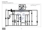
ELECTRIC SYSTEM
Circuit diagram (standard) (9822 0797 01)
S1
3
2
1
0
q
q
21
20
6
8
7
9
24
25
28
29
3
5
4
2
1
8«
7«
1«
2«
12
14
4«
3«
26
27
12«
34
35
9´,10´,11´
p
12V DC
5«
Temp
K1
General
alarm
(Lamp-
tester)
13«
15«
14«
11
10
13
11
9
9
9
15
14
Auxiliary
3
3
3
3
8
18
16
15
4
3
2
1
3
2
1
0
32
33
31
30
5
10A
23
22
19
17
6
7
6«
D- D+
B+
+
M
M1
K0
S2
S3
G2
G1
K4
F1
S1
K4
K3
S5
K1
H2
H1
K2
S4
K2
12
12
V1
h
12
12
12
12
12
12
12
K3
Y1
P1
K0
V2
10
13
The compressor is equipped with a
negative earthed system.
Summary of Contents for XAS 185 DD7
Page 2: ......
Page 22: ... 20 CONTINUOUS REGULATING SYSTEM UV UA VH RV SR AR CE ...
Page 67: ......
Page 68: ...www atlascopco com Atlas Copco Instruction Manual ...


