background image

- 57 -

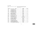
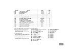
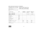
Maintenance schedule

(continuation of page 56)

Daily

50 hours after 
initial start-up

Every 6 months or 
500 hours

Yearly or every 
1000 hours

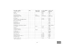
Radiator

Clean

Clean

Intercooler

Clean

Clean

Torque of wheel nuts

Check

Check

Check

Brake system (if installed)

Check/Adjust

Check/Adjust

Check/Adjust

Safety valve (10)

Test

Door hinges

Grease

Grease

Towing eye shaft or ball coupling and shaft

Grease

Grease

Bleed-off valve unloader

Replace

Oil stop valve

Clean

Rubber flexibles (13)

Check

Shut-down switches

Check

Pressure drop over oil separator element (2)

Replace/Measure

Fan V-belts (3)

Adjust

Adjust

Adjust

Fuel tank

Clean

Clean

Compressor oil (1) (8)

Change

Compressor oil filter (6)

Replace

Replace

Coolant (9) (5)

Analyse

Air filter element (1)

Replace

Engine oil (3) (4)

Change

Change

Engine oil filter (3)

Replace

Replace

Primary fuel filter (AC filter) (7)

Replace

Replace

Fuel prefilter (3) (7)

Replace

Replace

Crankcase breather filter

Clean

Clean

(to be continued on page 58)

Summary of Contents for XRVS 1300 CD7

Page 1: ...XRXS 567 Cd XRXS 1240 CD7 XRXS 607 Cd XRXS 1275 CD7 Engine CAT C18 XRVS 617 Cd XRVS 1300 CD7 XRVS 647 Cd XRVS 1350 CD7 Instruction Manual for Portable Compressors English ...

Page 2: ......

Page 3: ...LE AIR DIVISION www atlascopco com Printed matter N 9829 3007 48 07 2014 Instruction Manual for Portable Compressors XRXS 567 Cd XRXS 1240 CD7 XRXS 607 Cd XRXS 1275 CD7 XRVS 617 Cd XRVS 1300 CD7 XRVS 647 Cd XRVS 1350 CD7 ...

Page 4: ...tions additions or conversions made without the manufacturer s approval in writing While every effort has been made to ensure that the information in this manual is correct Atlas Copco does not assume responsibility for possible errors Copyright 2014 Atlas Copco Airpower n v Antwerp Belgium Any unauthorized use or copying of the contents or any part thereof is prohibited This applies in particular...

Page 5: ...ric system 22 3 3 Markings and information labels 24 4 Operating instructions 25 4 1 Parking towing and lifting instructions 25 4 1 1 Parking instructions Wagon 25 4 1 2 Towing instructions Wagon 26 4 1 3 Towbar levelling Wagon 26 4 1 4 Lifting instructions 26 4 2 Internal lighting 27 4 3 Preheater option 27 4 3 1 Description heating operation 27 4 4 Before starting 29 5 Starting Stopping 30 5 1 B...

Page 6: ...71 7 1 3 Replacing the filter element and the safety cartridge 71 7 1 4 Air receiver 72 7 1 5 Safety valve 72 7 2 Fuel system 72 7 2 1 Priming instructions 72 7 2 2 Replacing filter elements 73 7 2 3 Cleaning crankcase breather filter 73 7 2 4 Maintenance Quick action fuel couplings 74 7 3 Brake adjustments 74 7 3 1 Brake shoe adjustment Wagon 74 7 3 2 Brake adjustment wagon 75 8 Problem solving 7...

Page 7: ...ponents Skill level 3 Electrical technician An electrical technician is trained and has the same qualifications as both the operator and the mechanical technician In addition the electrical technician may carry out electrical repairs within the various enclosures of the unit This includes work on live electrical components Skill level 4 Specialist from the manufacturer This is a skilled specialist...

Page 8: ... kept clean i e as free as possible from oil dust or other deposits 7 To prevent an increase in working temperature inspect and clean heat transfer surfaces cooler fins intercoolers water jackets etc regularly See the Preventive maintenance schedule for the compressor 8 All regulating and safety devices shall be maintained with due care to ensure that they function properly They may not be put out...

Page 9: ...ilize the unit by placing chocks in front of and or behind the wheels When the tow bar can be positioned vertically the locking device must be applied and kept in good order The unit must always be used parked stored in a non publicly accessible area locked away from access by unauthorized persons 6 To lift heavy parts a hoist of ample capacity tested and approved according to local safety regulat...

Page 10: ...rwise stated in the Atlas Copco Instruction Book AIB Keep fuel away from hot parts such as air outlet pipes or the engine exhaust Do not smoke when fuelling When fuelling from an automatic pump an earthing cable should be connected to the unit to discharge static electricity Never spill nor leave oil fuel coolant or cleansing agent in or around the unit 14 All doors shall be shut during operation ...

Page 11: ...minals covered by insulating caps On electrically driven units the main switch shall be locked in open position and the fuses shall be taken out A warning sign bearing a legend such as work in progress do not supply voltage shall be attached to the fuse box or main switch 4 Before dismantling any pressurized component the compressor or equipment shall be effectively isolated from all sources of pr...

Page 12: ...unction properly 20 Maintenance and repair work should be recorded in an operator s logbook for all machinery Frequency and nature of repairs can reveal unsafe conditions 21 When hot parts have to be handled e g shrink fitting special heat resistant gloves shall be used and if required other body protection shall be applied 22 When using cartridge type breathing filter equipment ascertain that the...

Page 13: ...l specifications Safety reasons prohibit any other applications 3 National legislation requirements with respect to re inspection must be complied with 4 No welding or heat treatment of any kind is permitted to those vessel walls which are exposed to pressure 5 The vessel is provided and may only be used with the required safety equipment such as manometer overpressure control devices safety valve...

Page 14: ...sealing cooling and lubricating purposes The XRXS and XRVS type compressors can be equipped with two different gears resulting in different FAD Free Air Delivery Compressor oil system The oil is boosted by air pressure The system has no oil pump The oil is removed from the air in the air oil vessel at first by centrifugal force secondly through the oil separator element The vessel is provided with...

Page 15: ...e frame The standard compressor has a towbar with parking brakes Bodywork The bodywork has openings for the intake and outlet of cooling air and hinged doors for maintenance and service operations The bodywork is internally lined with sound absorbing material Lifting beam A lifting beam is accessible when a small door at the top is opened Serial number The serial number is stamped in at the front ...

Page 16: ... Main parts AFe CEhp CElp FCeo FFc ES OC CT FCc EP CLS R IC BH SN F AFS FT OFe E TB FFpc ETS FCft FLS CU DPce DPar DPeo DPosv DPce DPr DPoc AOV IPS MPV CP FLG AFce SV B AR FL OLG FPco RPS LV RV BS OFce OT ...

Page 17: ...e DPr Drain Plug Radiator E Engine EP Exhaust Pipe Reference Name ES Emergency Stop ETS Element Temperature Sensor F Fan FCeo Filler Cap engine oil FCft Filler Cap fuel tank FCc Filler Cap coolant FFpc Fuel Prefilter Caterpillar FFc Fuel Filter Caterpillar FL Flash Light FLG Fuel Level Gauge FLS Fuel Level Sensor FPco Filler Plug oil compressor element FT Fuel Tank IC Intercooler IPS Interstage Pr...

Page 18: ...Filter Switch AOV Air Outlet Valves AR Air Receiver BOV Blow Off Valve BVof Bypass Valve oil filter C Coupling CBE Cubicle for Electrical devices CElp Compressor Element low pressure CEhp Compressor Element high pressure CU Control Unit CV Check Valve DP Drain Plug E Engine F Fan FR Flow Restrictor LV Loading Valve MPV Minimum Pressure Valve OC Oil Cooler OFce Oil Filter compressor element OSV Oil...

Page 19: ... prevents the oil from flowing back into the compressor element The thermostatic by pass valve TBV starts opening when the oil temperature is 80 C 176 F when no Oiltronix is installed With installed Oiltronix the thermostatic by pass valve starts opening when the oil temperature is 40 C 104 F The compressor element has an oil gallery in the bottom of its casing The oil for rotor lubrication coolin...

Page 20: ... 20 PNEUMATIC REGULATING SYSTEM AR RV CEhp CElp BOV TV UA ...

Page 21: ...mum load speed and unloading speed the output of a screw compressor is proportional to the rotating speed 2 Air inlet throttling If the air consumption is equal to or exceeds the maximum air output the engine speed is held at maximum load speed and the throttle valve TV is fully open If the air consumption is less than the maximum air output air receiver pressure increases and the regulating valve...

Page 22: ... 36 35 M2 42 41 M 19 43 15A F2 43 24 40 38 39 40 M2 M1 F A B N3 END STOP 19 19 19 S2 15A F1 T IN 01 V IN 04 C1 H OUT 07 H OUT 10 L OUT 03 L OUT 02 L OUT 01 T IN 05 D IN 05 D IN 06 V IN 07 C4 B14 B15 C14 A13 A12 A11 B10 B5 C3 C2 D1 A9 C7 N1 B1 D13 D12 D11 A16 CONTROLLER 27M 27M 24 J1 P1 10 J1 P1 70 J1 P1 9 J1 P1 8 J1 P1 65 J1 P1 63 J1 P1 61 J1 P1 52 N2 J1 P1 42 J1 P1 34 J1 P1 50 J1 P1 48 ECM 24M K1...

Page 23: ...switch TT1 Temperature sensor PT1000 LP Element temperature TT2 Temperature sensor PT1000 HP element temperature TT3 Temperature sensor PT1000 Ambient temperature TT4 Temperature sensor PT1000 Aftercooler Y1 Loading Valve Y2 Blow off valve Y3 Air shut off valve Y4 Dual pressure valve X1 Optional equipment 1 Fused 24 VDC for Spare I O s and options 2 24 VDC power supply box for Spare I O s and opti...

Page 24: ... manual before starting Service every 24 hours Warning Part under pressure Do not stand on outlet valves Start Stop indication of switch Do not run the compressor with open doors Lifting permitted Use diesel fuel only 9 5 bar 138 psi Tyre pressure Sound power level in accordance with Directive 2000 14 EC expressed in dB A Fork lifting permitted Don t lift here Read the instruction manual before li...

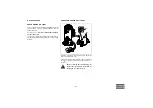
Page 25: ...wheels Locate the rear end of the compressor upwind away from contaminated wind streams and walls Avoid recirculation of exhaust air from the engine This can cause overheating and engine power decrease The operator is expected to apply all relevant Safety precautions Before putting the compressor in to use check the brake system as described in section Brake adjustments After the first 100 km trav...

Page 26: ...rn the nut 2 counter clockwise to decrease the spring load for lowering the towbar 3 Slide the bellows 1 over the nut LIFTING INSTRUCTIONS To lift the compressor use a lift truck or crane with sufficient capacity weight see indication on Dataplate See to it that the compressor will be lifted vertically and remains level Before towing the compressor ensure that the towing equipment of the vehicle m...

Page 27: ...s into control interval This is followed by the fan continuing to run for about 130 sec The signal lamp will stay lit during the control interval and also the waterpump continues to run If the heater does not ignite within 90 seconds after fuel pumping has started the start procedure must be repeated If the heater once again fails to ignite after 90 seconds a fault shut down is effected It is poss...

Page 28: ...ng pre settings By pressing button 1 once twice or three times you will select pre set time 1 2 or 3 The display shows e g pre set time 1 and symbol 1 Set the pre set period with buttons 2 or 3 With button 4 you can activate or deactivate the pre set period When activated the symbol ON appears and the symbol 1 2 or 3 Operation Switching ON the heater Press button 4 The heating period lasts minutes...

Page 29: ... any water and sediment from the fuel filters until clean fuel flows from the drain cock 8 Empty the dust trap of each air filter AF See section Replacing the filter element and the safety cartridge 9 Clogged air filter s will be indicated on the display of the control panel see section Fault codes If indicated replace the filter elements 10 Check coolant level in engine coolant top tank integrate...

Page 30: ...r It will cause damage in the control unit when using this switch for stopping Always first shut off the control unit and wait until the display is dark before switching the battery switch to position OFF CONTROL PANEL Do not disconnect power supply to control box in any way when the control box is switched on This will cause memory loss Do not switch off the circuit breaker when the control box i...

Page 31: ...commands the compressor to load depending on actual status command the compressor to switch to Not Loaded when in Load MEASUREMENTS VIEW button By pressing this button you can toggle between Measurements View and Main View SETTINGS VIEW button By pressing this button you can toggle between Settings View and Main View ALARMS VIEW button By pressing this button you can toggle between Alarms View and...

Page 32: ... 32 ENTER button Confirms stores the selection change BACK button Moves back one level or ignores the change ...

Page 33: ... when reaching the preset working pressure in the receiver 2 Check the air outlet temperature of the compressor element 3 Check the engine oil pressure the coolant temperature and display of control box 4 Avoid the engine running out of fuel Nevertheless if this happens fill the fuel tank and prime the fuel system to speed up starting see section Overview icons BATTERY SWITCH The compressor is equ...

Page 34: ... text 3 Compressor info Main View Indication Measuring View Indication Settings View Indication Alarm View Indication DPF REGENERATION High Exhaust System Temperature Means that the Diesel Particle Filter is being regenerated DPF REGENERATION NEEDED Means that the Diesel Particle Filter needs to be regenerated Please force DPF Regeneration ...

Page 35: ... dedicated icon PRESET Depending of which Pressure and or Flow setting is active the controller will show its dedicated icon Reference Name OPERATION MODE Local OPERATION MODE Remote OPERATION MODE PC Control OPERATION MODE Automatic OPERATION MODE Automatic Mode is active but the Auto Start and Auto Stop function are both inactive OPERATION MODE Block Mode ALARM Active not acknowledged Shutdown A...

Page 36: ...lected and entered to access the sublist MAIN VIEW LOADED 1300RPM 22 4bar 41 1286h 22 4 MEASUREMENTS LOADED 1300RPM 22 4bar 41 1286h Running Hours 1286h ECU Engine rpm 1300 rpm ECU Requested Speed 1300 rpm ECU DPF Soot Load 24 Vessel Pressure 22 4 bar HP Element Temperature 101 C Ambient Temperature 27 C SETTINGS LOADED 1300RPM 22 4bar 41 1286h 1000 GENERAL SETTINGS 2000 DIGITAL INPUTS 3000 VOLTAG...

Page 37: ...pening the blow down valve After power up the vessel pressure normally is low enough to proceed with the starting procedure The display now shows The machine is now ready to be started and is waiting for a start command Xc3003 v1 00 0 r7307 If the Power switch is turned to the OFF position while the vessel is blowing down it will not power down for as long as the vessel pressure is higher than 1 5...

Page 38: ...l preheat according to the parameters of the engine controller Active Buttons Stop Button to cancel Start command Load Button to activate Automatic Load Measurement View Button Settings View Button Alarms View Button MAIN VIEW PREPARING FOR START 0 0 RPM 0 0bar 41 1286h MAIN VIEW READING ENGINE DATA 0 0 RPM 0 0bar 41 1286h Active Buttons Stop Button to cancel Start command Load Button to activate ...

Page 39: ...ay shows The engine will run at minimum rpm until the engine s coolant temperature reaches 40 C with a minimum time of 15 seconds and a maximum time of 300 seconds 800RPM 324RPM 0RPM MAIN VIEW ENGINE CRANKING 324RPM 0 0bar 41 1286h Active Buttons Stop Button to cancel Start command Load Button to activate Automatic Load Measurement View Button Settings View Button Alarms View Button 120s 54s 0s MA...

Page 40: ...mand Load Button to activate Automatic Load Measurement View Button Settings View Button Alarms View Button MAIN VIEW ENGINE WARMING UP 1200RPM 2 9 bar 41 1286h 15s 7s 0s Active Buttons Stop Button to cancel Start command Load Button to initiate Automatic Load Measurement View Button Settings View Button Alarms View Button MAIN VIEW READY TO LOAD 4 6 1200RPM 4 6bar 41 1286h ...

Page 41: ...f the engine in order to meet the requested working pressure at the most economical fuel usage Active Buttons Stop Button to cancel Start command Load Button to cancel Load command Measurement View Button Settings View Button Alarms View Button MAIN VIEW BUILDING UP VESSEL PRESSURE 3 9 1200RPM 3 9bar 41 1286h Active Buttons Stop Button to cancel Start command Load Button to cancel Load command Mea...

Page 42: ...ight left arrows Press ENTER for 2 seconds and the middle section becomes green setting can be edited Press the UP DOWN arrows to set the requested pressure flow Press ENTER to confirm the new setting Some additional control features are available from Atlas Copco such as dual pressure switch remote start auto start remote pressure setting If interested please consult your Atlas Copco representati...

Page 43: ...topping When ENTER is pressed the HEST icon will appear See paragraph ALWAYS FIRST SHUT OFF THE CONTROLLER AND WAIT UNTIL THE DISPLAY IS DARK BEFORE SWITCHING THE BATTERY SWITCH TO POSITION OFF DIESEL PARTICULATE FILTER REGENERATION A full DPF Regeneration can take up to an hour HEST Icon MAIN VIEW ENGINE COOLING DOWN 1200RPM 19 4bar 41 1286h Press ENTER to allow DPF regen before stop DPF Soot Loa...

Page 44: ...attery switch for stopping Always first shut off the controller and wait until the display is dark before switching the battery switch to position OFF Diesel Particulate Filter Regeneration DIESEL PARTICULATE FILTER REGENERATION When the Diesel Particle Filter regeneration process is kept at its default AUTOMATIC setting then the DPF regeneration will be performed automatically when the Soot Load ...

Page 45: ...n LSR is ongoing while the soot load is less than 60 and the engine speed changes engine is stopped machine gets loaded then the DPF Regeneration process will be stopped If the Soot Load is higher than 30 when cooling down should start then an LSR is expected to be started the controller will ask If Enter is pressed within 10 seconds then the controller will allow the DPF regeneration to be comple...

Page 46: ...will show the DPF Regeneration Needed Icon In case of Inhibited DPF Regeneration the DPF Regeneration Needed Icon will overwrite the DPF Inhibited Icon Required Action Force DPF Regeneration see paragraph FORCE DPF REGENERATION When DPF Regeneration is started the DPF Regeneration Needed icon will disappear and the HEST icon will pop up SOOT LOAD reaches 90 only when DPF Regeneration is Inhibited ...

Page 47: ...nowledge the ECU DPF SOOT LOAD HIGH warning press Enter while in the Main View Force DPF Regeneration see paragraph FORCE DPF REGENERATION When DPF Regeneration is started the DPF Regeneration Needed icon will disappear and the HEST icon will pop up SOOT LOAD reaches 101 If still no action is taken the following warning appears and the controller will perform a controlled shutdown As soon as the e...

Page 48: ...enu Scroll one line down and Enter the 1140 ECU DPF REGENERATION menu OR Scroll down and Enter the MODE parameter Scroll down and Enter the AUTOMATIC setting Press the Back button 3 times to get back to the Main View DPF Regeneration setting will now be AUTOMATIC DPF REGENERATION Customer Level can now select between AUTO Regeneration INHIBIT Regeneration as long as the controller is not powered d...

Page 49: ... to the preferred month and press ENTER To change any other RTC setting the red figure is editable Scroll up down and press ENTER to change Use left right to shift between editable figures Now press BACK until you re back in the Main View or in the menu you require Set Language Press the SETTINGS VIEW button scroll to 1000 GENERAL SETTINGS press ENTER scroll to 1300 LANGUAGES ENTER the LANGUAGES m...

Page 50: ...n editable figure Now press BACK until you re back in the Main View or in the menu you require Go To Diagnostics Press the SETTINGS VIEW button scroll to 1000 GENERAL SETTINGS press ENTER scroll to 1150 DIAGNOSTICS ENTER the Diagnostics menu ENTER the ENABLE parameter scroll to ON and press ENTER Now the ECU will get PAC ignition and one can perform ECU diagnostics read DM1 List DM2 List ECU value...

Page 51: ...Warning Xc 2000 EMERGENCY STOP INPUT Shutdown Xc 2040 REMOTE EMERGENCY STOP Shutdown Xc 2070 COOLANT LEVEL LOW WARNING Warning Xc 2080 COOLANT LEVEL LOW SHUTDOWN Shutdown Xc 2090 ΔP AIRFILTERS HIGH Warning Xc 2100 NO PROJECTFILE DOWNLOADED Warning Xc 2752 NAM OILTRONIX BYPASS CIRCUIT Shutdown After Stop Xc 2762 NAM OILTRONIX CLOSED CIRCUIT Shutdown After Stop Xc 2772 NAM AIRXPERT OPENED CIRCUIT Sh...

Page 52: ...IRCUIT Warning Xc 4150 H P ELEMENT TEMPERATURE ALARM 1 Warning Xc 4160 H P ELEMENT TEMPERATURE ALARM 2 Controlled Stop Xc 4170 H P ELEMENT TEMPERATURE ALARM 3 Shutdown Xc 4190 H P ELEMENT TEMP SENSOR CIRCUIT Shutdown Xc 4220 AFTERCOOLER AIR TEMP SENSOR CIRCUIT Warning Xc 4230 AFTERCOOLER FREEZING DANGER Indication Xc 5200 AIR SHUT OFF Shutdown Xc 6190 CHARGE MONITORING FAIL Indication Xc 6327 STAR...

Page 53: ...ESSURE ECU COOLANT TEMPERATURE ECU COOLANT LEVEL ECU SUPPLY VOLTAGE ECU AMBIENT AIR TEMPERATURE ECU AIR INLET TEMPERATURE ECU FUEL TEMPERATURE ECU OIL TEMPERATURE ECU ENGINE SPEED ECU INJECTOR 1 ECU INJECTOR 2 ECU INJECTOR 3 ECU INJECTOR 4 ECU INJECTOR 5 ECU INJECTOR 6 ECU INJECTOR 7 ECU INJECTOR 8 ECU SOOT LOAD 6981 INLET VALVE POS FAILURE Shutdown Xc 7002 ECU COMMUNICATION Shutdown Xc 7007 ECU R...

Page 54: ...rminated by the emergency stop itself hardware as well as by the software When the emergency stop button 1 is pressed the operator can unlock the emergency stop by turning it counterclockwise The emergency stop button is only to be used in emergency situations not for stopping procedures 1 ...

Page 55: ... at your local Atlas Copco dealer SERVICE KITS A service kit is a collection of parts to fit a specific repair or rebuilding task It guarantees that all necessary parts are replaced at the same time which improves the uptime of the unit The order numbers of the Service Kits are listed in the Atlas Copco Parts List ASL STORAGE Run the compressor regularly e g twice a week until warm Load and unload...

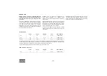
Page 56: ...g on application environment and quality of maintenance Maintenance schedule Daily 50 hours after initial start up Every 6 months or 500 hours Yearly or every 1000 hours XRXS 567 Cd XRXS 1240 CD7 XRXS 607 Cd XRXS 1275 CD7 2912 6075 05 2912 6076 06 XRVS 617 Cd XRVS 1300 CD7 XRVS 647 Cd XRVS 1350 CD7 2912 6075 05 2912 6075 06 Engine oil level Check Condensate 11 Drain Compressor oil level Check Cool...

Page 57: ... and shaft Grease Grease Bleed off valve unloader Replace Oil stop valve Clean Rubber flexibles 13 Check Shut down switches Check Pressure drop over oil separator element 2 Replace Measure Fan V belts 3 Adjust Adjust Adjust Fuel tank Clean Clean Compressor oil 1 8 Change Compressor oil filter 6 Replace Replace Coolant 9 5 Analyse Air filter element 1 Replace Engine oil 3 4 Change Change Engine oil...

Page 58: ...ge coolant every 5 years 6 Use Atlas Copco oil filters with by pass valve as specified in the parts list 7 Replace the fuel filters regularly Gummed or clogged filters mean fuel starvation and reduced engine performance The quality of the fuel determines the frequency of renewal 8 See section Oil specifications 9 The following part numbers can be ordered from Atlas Copco to check on inhibitors and...

Page 59: ... oil Then drain the synthetic oil again and fill again with new synthetic oil To set correct oil levels proceed as in normal instruction COMPRESSOR OIL Synthetic compressor oil PAROIL S Synthetic compressor oil PAROIL S68 Liter US gal Imp gal cu ft Order number can 5 1 3 1 1 0 175 1615 5950 01 can 20 5 3 4 4 0 7 1615 5951 01 barrel 210 55 2 46 7 35 1615 5952 01 container 1000 265 220 35 1604 7422 ...

Page 60: ...r and accumulate in the valve rocker cover area PAROIL releases excess heat efficiently whilst maintaining excellent bore polish protection to limit oil consumption PAROIL has an excellent Total Base Number TBN retention and more alkalinity to control acid formation PAROIL prevents Soot build up PAROIL is optimized for the latest low emission EURO 3 2 EPA TIER II III engines running on low sulphur...

Page 61: ...gine oil level according to the instructions in the Engine Operation Manual and if necessary top up with oil CHECK COMPRESSOR OIL LEVEL With the compressor standing horizontal check the level of the compressor oil The pointer of the oil level gauge 1 must register in the upper extremity of the green range Add oil if necessary Before removing the oil filler plug 2 ensure that the pressure is releas...

Page 62: ... plug 1 and top up with oil until the pointer of the oil level gauge 2 is in the upper part of the green area 4 Reinstall and tighten the filler plug 1 COMPRESSOR OIL AND OIL FILTER CHANGE The quality and the temperature of the oil determine the oil change interval The prescribed interval is based on normal operating conditions and an oil temperature of up to 100 C 212 F see section Preventive mai...

Page 63: ...top up with oil until the pointer of the oil level gauge is in the upper part of the green area COOLANT SPECIFICATIONS The use of the correct coolant is important for good heat transfer and protection of liquid cooled engines Coolants used in these engines must be mixtures of good quality water distilled or de ionised special coolant additives and if necessary freeze protection Coolant that is not...

Page 64: ...e radiator minimizing the risk for engine overheating and possible failure It reduces water pump seal wear and has excellent stability when subjected to sustained high operating temperatures PARCOOL EG is free of nitride and amines to protect your health and the environment Longer service life reduces the amount of coolant produced and needing disposal to minimise environmental impact PARCOOL EG T...

Page 65: ...RCOOL EG COOLANT CHECK In order to guarantee the lifetime and quality of the product thus to optimise engine protection regular coolant condition analysis is advisable The quality of the product can be determined by three parameters Visual check Verify the outlook of the coolant regarding colour and make sure that no loose particles are floating around pH measurement Check the pH value of the cool...

Page 66: ... 5 5 6 0 5 6 7 8 9 10 11 12 13 14 15 16 1 2 3 4 5 Example Total volume coolant Measured concentration In case of expansion tank at low level this quantity is to be filled without draining from the cooling system 1 Refractometer indication 20 C 33 2 Refractometer indication 22 C 3 Refractometer indication 25 C 4 Refractometer indication 30 C 5 Refractometer indication 36 C Liter Vol Liter PARCOOL E...

Page 67: ...al volume coolant Measured concentration In case of expansion tank at normal level this quantity is to be drained from the cooling system 1 Refractometer indication 20 C 33 2 Refractometer indication 22 C 3 Refractometer indication 25 C 4 Refractometer indication 30 C 5 Refractometer indication 36 C Liter Vol Liter PARCOOL EG Concentrate PN 1604 8159 00 4 8 12 16 20 24 28 32 36 40 44 48 52 56 60 6...

Page 68: ...e until normal engine operation temperature is reached Turn off the engine and allow to cool Recheck coolant level and add if necessary CLEANING COOLERS Keep the coolers 1 2 and 3 clean to maintain the cooling efficiency Service doors 4 are provided on both sides of the fan cowl to allow easy access to the fan side surface of the coolers Clean by air jet in the direction of the arrow Steam cleanin...

Page 69: ...and after charging a battery always check the electrolyte level in each cell if required top up with distilled water only When charging batteries each cell must be open i e plugs and or cover removed Apply with preference the slow charging method and adjust the charge current according to the following rule of thumb Battery capacity in Ah divided by 20 gives safe charging current in Amp BATTERY MA...

Page 70: ...he lock nut Dual pressure system option for XRXS and XRYS The dual pressure system has two regulating valves marked with I and II and a switch at the rear for selecting the lower I or higher II working pressure Set the regulating valve RV marked with I at a working pressure lower than the regulating valve marked with II This means the handle of RV I should be scewed in less than the handle of RV I...

Page 71: ...dge 3 is an indication of a malfunctioning filter element 3 Reassemble in reverse order of dismantling 4 Inspect and tighten all air intake connections 1 Snap clips 4x 4 Filter element 2 Dust trap cover 5 Filter housing 3 Safety cartridge 6 Vacuator valve The Atlas Copco air filters are specially designed for the application The use of non genuine air filters may lead to severe damage of the engin...

Page 72: ... in order to purge trapped air see paragraph Overview icons The fuel system should be primed under the following conditions Compressor is put in operation for the first time Running out of fuel Storage Replacement of the fuel filter Daily drain condensate 2 1 All adjustments or repairs are to be done by an authorized representative of the safety valve 2 supplier see section Specific safety precaut...

Page 73: ...mp 5 Close vent when fuel begins to purge 8 Check for leaks retighten if necessary Drain instructions 1 Open bowl drain valve 1 operate pump 5 and pump water out 2 Close drain valve 1 CLEANING CRANKCASE BREATHER FILTER 1 After switching off the engine let it cool down for about 30 minutes 2 Open the clasps 2 and carefully separate the bowl from the head Be aware that hose 3 is still attached 3 Tak...

Page 74: ...t Operate the system at maximum operating pressure and check for possible malfunctions and freedom from leaks Personnel must avoid potential hazardous areas while testing and using the system Replacement intervals Specific replacement intervals must be considered based on previous service life government or industry recommendations or when failures could result in unacceptable downtime damage or i...

Page 75: ...e lever several times by hand with a force of 200 to 300 N and put it back into the not engaged tooth 1 position Adjust the turnbuckle 8 as described above Testing the parking brake For testing the parking brake apply the parking brake lever Brake power must be reached between the 6th and 14th tooth of the toothed segment Z 10 Z 9 7 Y Y 11 11 8 Z 14 6 1 Tighten all lock nuts 11 Torque 24 Nm ...

Page 76: ... an Atlas Copco Service representative Blow down valve stuck in open position Check and correct as necessary Loading valve LV leaking past O ring With compressor running at max load speed disconnect hose leading to unloader If air leaks from the hose remove and inspect loading valve Replace damaged or worn O rings Oil separator element clogged Have element removed and inspected by an Atlas Copco S...

Page 77: ...ews first remove the short screws then release the spring tension unscrewing the long ones Minimum pressure valve malfunctioning Remove and inspect valve Blow off valve malfunctioning Remove and inspect valve Possible faults Corrective actions Engine oil pressure too low Refer to the engine instruction manual Compressor or engine overheating See corrective actions Compressor overheating Fuel tank ...

Page 78: ...nt compressor cooling Locate compressor away from walls when banked with other compressors leave space between them Oil cooler clogged externally Clean oil cooler Refer to section Cleaning coolers Oil cooler clogged internally Consult Atlas Copco Oil filters clogged Replace oil filters Oil level too low Check oil level Top up with recommended oil if necessary Thermostatic by pass valve remains stu...

Page 79: ...oblem Heater shuts off Problem Control unit locked Possible faults Corrective actions No fuel Check fuel level Fuse blown Check fuse Bad electrical contact Check electrical wiring Blocked air duct or exhaust gas duct Check combustion air duct and exhaust gas duct Glow plug defective Replace glow plug Fan motor defective Replace fan motor Possible faults Corrective actions Overheating Cool down and...

Page 80: ...pressor to a truck for more flexibility or to a frame when it is to be used permanently in an installation In combination with the support mounted it is also possible to integrate larger fuel tank to get larger intervals between two fuel supply actions SKID LARGE FUELTANKS The skid is ideal in circumstances where the site is impossible to reach by truck It allows transportation by crane or fork li...

Page 81: ...er gives an extra protection to the fuel combustion system ELECTRIC REFUEL PUMP The electric refuel pump makes it easy to refuel the compressor on site when refuelling from tanks or containers This option also contains a suction hose with strainer When switched on the electric refuel pump will be automatically switched off when the tank is full the tank from which is being refulled is empty ...

Page 82: ...park arrestor is an addition to the exhaust that makes it possible to operate the compressor in hazardous environments like refineries where there is a possibility that inflammable fumes can be released The spark arrestor prevents any hot burning particles from getting into the open air PREHEATER The preheater is a device for preheating the cooling fluid before starting when operating at low tempe...

Page 83: ...ine max RPM is exceeded a pneumatically controlled solenoid valve closes off the air inlet and the fuel supply to the engine is cut OILTRONIX The OILTRONIX is an Electronic Oil Management System for compressors providing an optimal oil injection temperature that reduces the condensation of water in the oil This will result in a longer life of components in the compressor system Because of the OILT...

Page 84: ...orking conditions and the output required This option contains one regulating valve REGULATING SYSTEM DUAL PRESSURE NO FUEL EXPERT With this option it is possible to set the pressure to two particular pressures REGULATING SYSTEM DUAL PRESSURE FUEL EXPERT This option combines the dual pressure regulating system with the fuel optimising system thus saving on fuel costs ...

Page 85: ...hand held pneumatic tools PRESSURE REGULATOR ASME A pressure regulating system according to US standards for reducing the operating pressure It will limit the operating pressure to 7 bar and allow the operation of hand held pneumatic tools FORK LIFT SLOTS With fork lift slots the compressor can easily be moved with a fork lift truck on building sites where it is impossible to use a towing truck ...

Page 86: ...g air an active charcoal filtration unit 3 can be specified with the after cooler package This removes oil and oil vapour content to 0 003 mg m3 REMOTE START The remote start allows the user to start stop the compressor and switch to load noload by radiosignal This is particularly comfortable when the compressor can not be positioned directly at the job site because of blocking by buildings or oth...

Page 87: ...100 M14 210 155 M16 345 255 Assemblies Torque value Nm lbf ft Axles to frame Wheel nuts 270 200 Bolts front axle frame 205 152 Bolts rear axle frame 205 152 Compressor to frame Bolts elements gear casing 46 34 Bolts elements support 80 60 Bolts support buffer 205 152 Bolts buffer frame 80 60 Engine to frame Bolts engine support 205 152 Bolts support buffer 46 34 Bolts buffer frame 23 17 Lifting be...

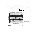
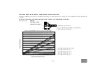
Page 88: ... effective working pressure bar e 30 25 psi 435 363 Designation XRXS 567 Cd XRXS 1240 CD7 XRXS 607 Cd XRXS 1275 CD7 XRVS 617 Cd XRVS 1300 CD7 XRVS 647 Cd XRVS 1350 CD7 Minimum effective receiver pressure bar e 19 16 psi 276 232 Maximum effective receiver pressure compressor unloaded bar e 32 27 psi 464 392 Maximum ambient temperature at sea level without aftercooler C 50 50 F 122 122 with aftercoo...

Page 89: ...aftercooler l s 549 602 588 611 cfm 1 163 1 276 1 246 1 295 Fuel consumption at 100 FAD Fuel expert kg h 84 3 88 6 82 4 85 4 lb h 185 8 195 3 181 7 188 3 No Fuel expert kg h 84 3 88 6 82 4 85 4 lb h 185 8 195 3 181 7 188 3 at 75 FAD Fuel expert kg h 67 0 67 9 64 7 67 0 lb h 147 7 149 7 142 6 147 7 No Fuel expert kg h 73 9 78 5 70 0 72 5 lb h 162 9 173 1 154 3 159 8 at 50 FAD Fuel expert kg h 54 8 ...

Page 90: ... Compressed air temperature at outlet valve without aftercooler C 100 100 100 100 F 212 212 212 212 with aftercooler C 35 35 35 35 F 95 95 95 95 Noise level Sound pressure level LP complies with ISO 2151 under free field conditions at 7 m distance dB A Sound pressure level LP complies with EPA under free field conditions at 7 m distance dB A 76 76 76 76 Sound power level LW complies with 2000 14 E...

Page 91: ...0 3 281 6 562 9 843 13 124 0 1000 2000 3000 4000 10 0 10 20 30 40 50 14 32 50 68 86 104 122 30 bar 435 psi Altitude m Altitude ft Temperature F Temperature C XRVS 617 Cd XRVS 1300 CD7 XRVS 647 Cd XRVS 1350 CD7 0 3 281 6 562 9 843 13 124 0 1000 2000 3000 4000 10 0 10 20 30 40 50 14 32 50 68 86 104 122 25 bar 363 psi Altitude m Altitude ft Temperature F Temperature C ...

Page 92: ... C18 Coolant Liquid Number of cylinders 6 Bore mm 145 in 5 71 Stroke mm 183 in 7 2 Swept volume l 18 1 cu in 1104 5 Output acc to DIN 6271 at normal shaft speed kW 429 hp 575 3 Load factor 100 Designation All units Capacity of oil sump Initial fill l 60 US gal 15 85 Refill max 1 l 58 US gal 15 32 Capacity of cooling system l 52 US gal 13 74 ...

Page 93: ...nge Designation All units Capacity of compressor oil system l 82 US gal 21 66 Net capacity of air receiver l 143 US gal 37 78 Capacity of fuel tank standard l 975 US gal 257 6 Capacity of fuel tanks with skid or support mounted with option large fuel tanks l 1550 US gal 409 5 Air volume at inlet grating approx 1 m3 s 13 9 cu ft s 491 Designation All units Flow rate l m 50 US gal m 13 Self priming ...

Page 94: ...8 x 89 37 Skid m 4 56 x 2 25 x 2 44 inch 179 53 x 88 58 x 96 06 Designation All units Weight dry Wagon kg 7200 lb 15875 Tandem EU kg 8605 lb 18971 Support mounted option large fuel tank kg 6555 6685 lb 14450 14740 Skid option large fuel tank kg 6775 6095 lb 14940 15225 Weight wet incl fuel Wagon kg 8200 lb 18080 Tandem EU kg 10100 lb 22267 Support mounted option large fuel tank kg 7555 8180 lb 166...

Page 95: ...Dataplate 95 ...

Page 96: ...07 Cd XRXS 1275 CD7 XRVS 617 Cd XRVS 1300 CD7 XRVS 647 Cd XRVS 1350 CD7 Set pressure bar e 35 30 psi 508 435 Design temperature C 130 130 F 266 266 Designation Standard Cold start equipment Design pressure bar e 35 35 psi 508 508 Design temperature max C 130 130 F 266 266 Design temperature min C 25 25 F 13 13 Volume l 143 143 US gal 37 7 37 7 Imp gal 31 5 31 5 cu ft 5 5 ...

Page 97: ... 97 PARTS SUBJECTED TO CAT I AND COVERED BY THE MACHINE DIRECTIVE 89 392 EC All other parts PARTS SUBJECTED TO ART I PARAGRAPH 3 3 All other parts ...

Page 98: ...aterials for recycling in the future is forseen DISPOSAL OF MATERIALS Dispose contaminated substances and material separately according to local applicable environmental legislations Before dismantling a machine at the end of its operating lifetime drain all fluids and dispose of according the applicable local disposal regulations Remove the batteries Do not throw batteries into the fire explosion...

Page 99: ... 99 Maintenance Log Compressor Customer Serial number Service hours Maintenance action Date By initials ...

Page 100: ... 100 ...

Page 101: ......

Page 102: ......

Reviews: