background image

12. The electrical connections must correspond to the applicable codes. The machines must be

earthed and protected against short circuits by fuses in all phases. A lockable power
isolating switch must be installed near the compressor.

13. On machines with automatic start/stop system or if the automatic restart function after

voltage failure is activated, a sign stating "This machine may start without warning" must be
affixed near the instrument panel.

14. In multiple compressor systems, manual valves must be installed to isolate each

compressor. Non-return valves (check valves) must not be relied upon for isolating pressure
systems.

15. Never remove or tamper with the safety devices, guards or insulation fitted on the machine.

Every pressure vessel or auxiliary installed outside the machine to contain air above
atmospheric pressure must be protected by a pressure relieving device or devices as
required.

16. Piping or other parts with a temperature in excess of 70˚C (158˚F) and which may be

accidentally touched by personnel in normal operation must be guarded or insulated. Other
high temperature piping must be clearly marked.

17. For water-cooled machines, the cooling water system installed outside the machine has to

be protected by a safety device with set pressure according to the maximum cooling water
inlet pressure.

18. If the ground is not level or can be subject to variable inclination, consult the manufacturer.
19. If the device is a dryer and no free extinguishing system is present in the air net close to the

dryer, safety valves must be installed in the vessels of the dryer.

Also consult following safety precautions: 

Safety precautions during operation

 and

Safety precautions during maintenance

.

These precautions apply to machinery processing or consuming air or inert gas.
Processing of any other gas requires additional safety precautions typical to the
application which are not included herein.
Some precautions are general and cover several machine types and equipment; hence
some statements may not apply to your machine.

1.4

Safety precautions during operation

All responsibility for any damage or injury resulting from neglecting these precautions, or
non observance of the normal caution and care required for installation, operation,
maintenance and repair, even if not expressly stated, will be disclaimed by the
manufacturer.

Precautions during operation

1. Never touch any piping or components of the machine during operation.
2. Use only the correct type and size of hose end fittings and connections. When blowing

through a hose or air line, ensure that the open end is held securely. A free end will whip
and may cause injury. Make sure that a hose is fully depressurized before disconnecting it.

3. Persons switching on remotely controlled machines shall take adequate precautions to

ensure that there is no one checking or working on the machine. To this end, a suitable
notice shall be affixed to the remote start equipment.

4. Never operate the machine when there is a possibility of taking in flammable or toxic fumes,

vapors or particles.

5. Never operate the machine below or in excess of its limit ratings.

Instruction book

AIF999999

7

Summary of Contents for ZR 200

Page 1: ...Instruction book AIF999999 ZR 200 ...

Page 2: ......

Page 3: ...thereof is prohibited This applies in particular to trademarks model denominations part numbers and drawings This instruction book is valid for CE as well as non CE labelled machines It meets the requirements for instructions specified by the applicable European directives as identified in the Declaration of Conformity 2020 11 www atlascopco com ...

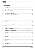
Page 4: ...ription 11 2 1 INTRODUCTION 11 2 2 AIR SYSTEM 13 2 3 COOLING AND CONDENSATE DRAIN SYSTEM 15 2 4 ELEKTRONIKON REGULATED DRAIN ERD 16 2 5 OIL SYSTEM 18 2 6 REGULATING SYSTEM 19 2 7 CONNECTIVITY AND SMARTLINK 21 3 Elektronikon Touch controller 24 3 1 CONTROLLER 24 3 2 CONTROL PANEL 26 3 3 ICONS USED 27 3 4 MAIN SCREEN 31 3 5 QUICK ACCESS SCREEN 32 3 6 MENU SCREEN 33 3 7 DATA MENU 35 3 8 SERVICE MENU ...

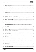
Page 5: ...PONENTS 65 4 7 COOLING WATER REQUIREMENTS 65 4 8 GENERAL PICTOGRAPHS 70 5 Operating instructions 72 5 1 INITIAL START UP 72 5 2 BEFORE STARTING 79 5 3 ROUTINE STARTING 81 5 4 STARTING AFTER EMERGENCY STOP OR SHUTDOWN 83 5 5 DURING OPERATION 84 5 6 CHECKING THE DISPLAY 85 5 7 MANUAL LOADING UNLOADING 86 5 8 STOPPING 87 5 9 TAKING OUT OF OPERATION 88 6 Maintenance 89 6 1 PREVENTIVE MAINTENANCE SCHED...

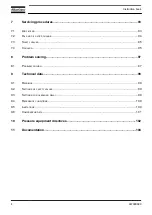
Page 6: ... 95 8 Problem solving 97 8 1 PROBLEM SOLVING 97 9 Technical data 99 9 1 READINGS 99 9 2 SETTINGS OF SAFETY VALVES 99 9 3 SETTINGS FOR OVERLOAD RELAY 99 9 4 REFERENCE CONDITIONS 100 9 5 LIMITATIONS 100 9 6 COMPRESSOR DATA 101 10 Pressure equipment directives 102 11 Documentation 104 Instruction book 4 AIF999999 ...

Page 7: ...f the voltage Depressurize the machine Lock Out Tag Out LOTO Open the power isolating switch and lock it with a personal lock Tag the power isolating switch with the name of the service technician On units powered by a frequency converter wait 10 minutes before starting any electrical repair Never rely on indicator lamps or electrical door locks before maintenance work always disconnect and check ...

Page 8: ...siccant bags must be removed before connecting the pipes 5 Air hoses must be of correct size and suitable for the working pressure Never use frayed damaged or worn hoses Distribution pipes and connections must be of the correct size and suitable for the working pressure 6 In case the device is a compressor the aspirated air must be free of flammable fumes vapors and particles e g paint solvents th...

Page 9: ...ystem is present in the air net close to the dryer safety valves must be installed in the vessels of the dryer Also consult following safety precautions Safety precautions during operation and Safety precautions during maintenance These precautions apply to machinery processing or consuming air or inert gas Processing of any other gas requires additional safety precautions typical to the applicati...

Page 10: ... tamper with the sound damping material 12 Never remove or tamper with the safety devices guards or insulations fitted on the machine Every pressure vessel or auxiliary installed outside the machine to contain air above atmospheric pressure shall be protected by a pressure relieving device or devices as required 13 Yearly inspect the air receiver Minimum wall thickness as specified in the instruct...

Page 11: ...with open flame for inspecting the interior of a machine pressure vessel etc 14 Make sure that no tools loose parts or rags are left in or on the machine 15 All regulating and safety devices shall be maintained with due care to ensure that they function properly They may not be put out of action 16 Before clearing the machine for use after maintenance or overhaul check that operating pressures tem...

Page 12: ...ents e g drain oil from oil containing parts 4 Refer to the disposal topic mentioned below Disposal of electrical and electronic appliances WEEE This equipment falls under the provisions of the European Directive 2012 19 EU on waste electrical and electronic appliances WEEE and may not be disposed as unsorted waste The equipment is labelled in accordance with the European Directive 2012 19 EU with...

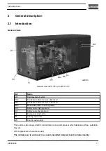
Page 13: ...5 Elektronikon Mk5 Touch regulator SVh Safety valve high pressure SVl Safety valve low pressure S2 Emergency stop button WI Cooling water inlet WO Cooling water outlet This unit is a two stage electric motor driven screw compressor which delivers oil free pulsation free air ZR compressors are water cooled The compressor is enclosed in a sound insulated bodywork and includes mainly Instruction book...

Page 14: ...he motor gear casing unit is supported on the frame by vibration dampers ElektronikonTM control system The compressor is controlled by an electronic regulator which Controls the operation of the compressor Reduces the power consumption Warns the operator in case of an abnormal operating condition Protects the compressor Monitors components subject to service If activated the regulator can automati...

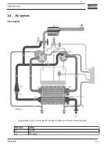
Page 15: ...2 2 Air system Flow diagram Flow diagram of ZR 110 up to ZR 275 and ZR 132 VSD up to ZR 315 VSD compressors Reference Name AF Air filter AO Air outlet Instruction book AIF999999 13 ...

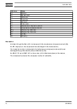
Page 16: ...Air drawn through the filter AF is compressed in the low pressure compressor element El On ZR compressors the compressed air is discharged to the intercooler Ci The cooled air is further compressed in the high pressure compressor element Eh and discharged through the silencer AS and aftercooler Ca On ZR ZT 110 up to ZR ZT 275 a check valve CV is fitted downstream of the silencer The compressed air...

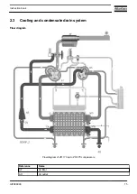
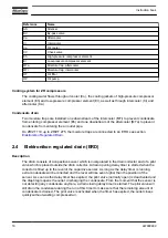
Page 17: ...2 3 Cooling and condensate drain system Flow diagram Flow diagram of ZR 110 up to ZR 275 compressors Reference Name AF Air filter AO Air outlet Instruction book AIF999999 15 ...

Page 18: ...Elektronikon Regulated Drain 2 4 Elektronikon regulated drain ERD Description The drain consists of a capacitive sensor which is incorporated in the drain collector and of a pilot valve which is placed outside the drain collector A drain opening delay timer is started when the collector is filled up to the level of the capacitive sensor As long as the delay timer is running extra condensate will b...

Page 19: ... loose their set point Special attention must be paid to the correct wiring of the different level switches and solenoid valves The output of the level switch can be called up on the screen of the Elektronikon regulator The reading does not indicate whether the solenoid valve is open or closed but indicates whether the level switch is detecting water in the collector Since there is a drain opening...

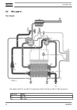
Page 20: ...2 5 Oil system Flow diagram Flow diagram of ZR 110 up to ZR 275 compressors and ZR 132 VSD up to ZR 315 VSD compressors Reference Name AF Air filter AO Air outlet Instruction book 18 AIF999999 ...

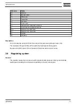
Page 21: ...Description Oil is circulated by pump OP from the sump of the gear casing through cooler Co The oil passes through oil filter OF towards the bearings and timing gears By pass valve BV opens if the oil pressure should rise above a given value 2 6 Regulating system General The regulator keeps the net pressure within programmable pressure limits by automatically loading and unloading the compressor d...

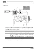
Page 22: ...pressure is vented from chamber 1 of unloader UA through solenoid valve Y1 and chamber 3 towards the inlet of compressor element El 2 As there is no longer any pressure difference between chambers 1 and 3 plunger 2 returns by spring force keeping full load no load valve TV closed and unloading valve UV open 3 Compressed air between check valve CV and valve UV is blown off through silencer US Check...

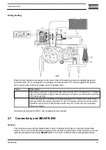
Page 23: ...ntercooler pressure is building up causing diaphragm 4 to switch to the right As the pressure difference between chambers 1 and 3 increases plunger 2 moves further against the spring force until full load no load valve TV is fully open and unloading valve UV closed Air delivery is resumed 100 the compressor runs loaded 2 7 Connectivity and SMARTLINK General The machine comes with an Elektronikon T...

Page 24: ...Service rules out all uncertainties Scheduling maintenance visits becomes as simple and easy as it should be the service log book is always just one click away and the online link with Atlas Copco allows to request and quickly receive quotes for spare parts or additional services This product level is free of charge and available for 3 years following the machine purchase SMARTLINK Uptime SMARTLIN...

Page 25: ...will receive an e mail with login credentials Go to the SMARTLINK web site http www atlascopco com smartlink log in with the user credentials Enjoy SMARTLINK In case more SMARTLINK ready machines are available you can add these via My Profile Instruction book AIF999999 23 ...

Page 26: ...ammable settings e g the unloading and loading pressures for fixed speed units the setpoint for units with frequency converter the minimum stop time the maximum number of motor starts and several other parameters are taken into account The controller stops the unit whenever possible to reduce the power consumption and restarts it automatically when the net pressure decreases If the expected unload...

Page 27: ... stop button to stop the unit and wait until the unit has stopped Switch off the voltage inspect the unit and remedy if necessary The warning message will disappear as soon as the warning condition disappears Service warning A number of service operations are grouped as a Service Plan Each Service Plan has a programmed time interval If the service timer exceeds a programmed value this will be indi...

Page 28: ... by touch 2 Warning sign Flashes in case of a shut down and is lit in case of a warning condition 3 Service sign Lit when service is needed 4 Operation sign Lit when the unit is running in automatic operation 5 Voltage sign Indicates that power is switched on 6 Stop button Stops the unit 7 Start button Starts the unit The operation sign 4 lights up The controller is operative Instruction book 26 A...

Page 29: ...con Data Status Inputs Outputs Counters Aux Equipment Parameters Converters Service Service Overview Service Plan Service History Service functions Clean Screen Week Timer Week Remaining Running Time Event History Saved Data Instruction book AIF999999 27 ...

Page 30: ...s Aux Equipment Parameters Converter s Fan Internal SmartBox Auto Restart Controller Settings Network Settings Ethernet Settings CAN Settings Localisation Language Date Time Units User Password Help Information Status icons Icon Description Motor Stopped Instruction book 28 AIF999999 ...

Page 31: ...iled to Load Running Loaded Wait Manual Stop Machine Control Mode Local Machine Control Mode Remote Machine Control Mode LAN Automatic Restart After Voltage Failure Week Timer Active System icons Icon Description Basic User Advanced User Service User Antenna 25 Instruction book AIF999999 29 ...

Page 32: ...tenna 100 Change between screens indication Energy recovery Dryer Element Drain s Analogue Output Menu Reset Auto Restart Filter s Cooler Valve s Power Meter Input icons Icon Description Pressure Instruction book 30 AIF999999 ...

Page 33: ...cally after a few minutes when there is no touch input Description Reference Designation Function 1 Home button The home button is always shown and can be tapped to return to the main screen 2 Screen information On the main screen the screen information bar shows the serial number of the machine When scrolling through menus the name of the current menu is shown 3 Access level button The access lev...

Page 34: ...11 These fields can contain a history chart an input or a counter value depending on the type of the machine Tap the field to view the type of measurement This will be shown in the screen information bar Examples of inputs Ambient temp Outlet Dryer dewpoint Examples of counters Running hours Load relay Loaded hours 12 Menu button The menu button is always shown and can be tapped to go to the menu ...

Page 35: ...maining running time can be set and modified by tapping this icon Internal SmartBox The reception quality of the internal antenna can be monitored Each bar represents 25 reception strength If the four bars are filled the reception strength is 100 If only one bar is filled the reception strength is just 25 Auto restart Auto restart can be activated by tapping this icon 3 6 Menu screen Function This...

Page 36: ...rol parameters can be changed through this menu Auxiliary equipment parameters can also be changed The Auto restart function can be set through this menu This function is password protected 6 Controller settings Network settings Localisation settings and a User password can be set through this menu There is also a Help page available and the Controller information can be shown Menu structure Opera...

Page 37: ...y tapping the icons Procedure To enter the Data menu screen 1 Tap the Menu button 2 Tap the Data icon Description Reference Designation 1 Status menu 2 Inputs menu 3 Outputs menu 4 Counters menu 5 Auxiliary equipment menu Status menu Tap the Status icon to enter the Status menu This menu shows the current status of the unit Instruction book AIF999999 35 ...

Page 38: ... This menu shows information about all the inputs Outputs menu Tap the Outputs icon to enter the Outputs menu This menu shows information about all the outputs Voltage free outputs may only be used to control or monitor functional systems They should NOT be used to control switch or interrupt safety related circuits Check the maximum allowed load on the label Stop the unit and switch off the suppl...

Page 39: ...s menu shows an overview of all auxiliary equipment fitted 3 8 Service menu Function This screen is used to display the following submenus Service Service functions Only visible as advanced user Clean screen These submenus can be entered by tapping the icons Procedure To enter the Service menu screen 1 Tap the Menu button 2 Tap the Service icon Instruction book AIF999999 37 ...

Page 40: ... tapping icon 1 The service plan can be viewed by tapping icon 2 Through this menu the service plan can be modified 1 Tap the desired service plan A selection screen will pop up 2 Change the Running Hours by tapping or 3 Confirm by tapping V or decline by tapping X The service history can be viewed by tapping icon 3 When a service plan interval is reached a message will appear on the screen When s...

Page 41: ... of the touchscreen The touchscreen and the start and stop button become inactive for 15 seconds 3 9 Week timer menu Function This screen is used to set up to 4 different week timers with each up to 8 settings per day The week timers can be activated through this screen A Remaining Running Time can be set from 5 up to 240 minutes Procedure To enter the Week Timer menu screen 1 Tap the Menu button ...

Page 42: ...lection screen pops up The user can change the remaining time by tapping or and can confirm by tapping V or decline by tapping X 5 Add setting A selection screen pops up The user can change the setting by swiping up or down and confirm by tapping V or decline by tapping X 3 10 Event history menu Function This screen is used to display the saved data in case of an alarm These submenus can be entere...

Page 43: ...ormation reflecting the status of the unit when the shutdown occurred 3 11 Machine settings menu Function This screen is used to display the following submenus Alarms Regulation Control Parameters Only visible if the machine has adaptable parameters Aux Equipment parameters Auto Restart These submenus can be entered by tapping the icons Procedure To enter the Machine settings menu screen 1 Tap the...

Page 44: ...ap the Alarms icon to enter the Alarms menu A list of all alarms is shown When pressing on one of the items in this list the warning and or shutdown levels are shown for this alarm Regulation menu Tap the Regulation icon to enter the Regulation menu Setpoints or pressure bands can be modified through this menu Modify a setting Instruction book 42 AIF999999 ...

Page 45: ...ing When tapping a list item a selection screen pops up The user can modify the setting by tapping or and can confirm by tapping V or decline by tapping X Auxiliary equipment parameters menu Tap the Aux Equipment Parameters icon to enter the auxiliary equipment parameters menu This menu shows an overview of all the auxiliary equipment fitted Through this menu the parameters of the auxiliary equipm...

Page 46: ...by tapping V or decline by tapping X Modify a setting When clicking a list item a selection screen pops up The user can modify the setting by tapping or and can confirm by tapping V or decline by tapping X 3 12 Controller settings menu Function This screen is used to display the following submenus Network Settings Localisation User Password Help Information These submenus can be entered by tapping...

Page 47: ...turned off the settings can be modified Modify a setting When tapping a list item a selection screen pops up The user can modify the setting by tapping or and can confirm by tapping V or decline by tapping X Change a selection When tapping a list item a selection screen pops up The user can change the selection by swiping up or down and confirm by tapping V or decline by tapping X Localisation men...

Page 48: ...the User Password icon to enter the User Password menu The user password can be activated or deactivated through this menu Enter and confirm a user password to activate repeat to deactivate Enter a password When tapping a password protected item a selection screen pops up The user can enter the password by swiping up or down to select the desired number Once the 4 digits are entered the user can c...

Page 49: ... Access Level button at the upper right corner of the screen Description Reference Designation Function 1 User A basic set of parameters is visualized no password required 2 Service A basic set of parameters can be modified no password required 3 Full This access level is not accessible to end users 4 Decline Tap to decline the selected user level 5 Confirm Tap to confirm the selected user level I...

Page 50: ...1 now shows the current status of the unit instead of the machine serial number The Received Signal Strength Indicator RSSI value is now shown in the Internal SmartBox menu See Quick access screen In the service menu an extra menu item is now available See Service menu Instruction book 48 AIF999999 ...

Page 51: ...4 Installation 4 1 Dimension drawing Dimensions Dimension drawing of ZR 160 up to ZR 275 Pack and ZR 250 315 VSD Pack compressors in imperial units Instruction book AIF999999 49 ...

Page 52: ...5 Compressed air outlet 3 150 Lbs acc ANSI B16 5 Scale 1 5 30 Compressed air outlet 36 Rear side view 37 Grating only for option separate air intake 38 Voltage supply entrance for VSD compressors possibility 2 41 Opening for transportation 42 4 slotted holes to pull the compressor out of a container 43 Net mass of a standard compressor 44 Net mass of a compressor without a motor 51 Center of gravi...

Page 53: ...4 2 Installation proposal Compressor room example Installation proposal for ZR 160 Pack up to ZR 275 Pack in inch 1 Minimum free area to be reserved 2 Ventilation proposal Instruction book AIF999999 51 ...

Page 54: ...5 x p x dp Qc1 85 Symbol Explanation d Inner diameter of the outlet pipe in inch dp Pressure drop recommended maximum 1 45 psi L Length of outlet pipe in ft p Absolute pressure at the compressor outlet in psi g Qc Free air delivery of the compressor in cfm It is strongly recommended to make the connection of the compressor air outlet pipe on top of the main air net pipe in order to minimize carry ...

Page 55: ...ate collector The drain pipes must not dip into the water in the collector It is recommended to provide a funnel to allow visual inspection of the condensate flow 6 Elektronikon control system with control panel 7 See Electric cable size fuses and cable length for the recommended size of the supply cables Check that the electrical connections meet local codes The installation must be earthed and p...

Page 56: ... Axial ΔL Lateral ΔR Drawing reference Description A Atlas Copco compressor pipe end B Customer installation pipe end Angular misalignments Δα are NOT allowed Instruction book 54 AIF999999 ...

Page 57: ...tion 1 Compression 2 Stretch Do NOT operate outside of the black polygon Do NOT exceed the misalignment tolerances to avoid compensator damage The piping system of the customer should be designed to fit the misalignment tolerances both during standstill and operation Temperature correction factors Medium temperature F Correction factor for maximum working pressure of the compensator 32 1 Instructi...

Page 58: ...orque the bolts crosswise up to the value mentioned in the table below Mind the parallelism of the sealing Excessive torque will damage the sealing DN inch Step 1 Step 2 lbfin Step 3 lbfin 2 3 hand tight 443 708 4 12 hand tight 443 885 14 20 hand tight 443 1551 Do s and don ts The supplied compensators are NOT designed to carry the weight of the mounted customer pipe end to work as a damper for un...

Page 59: ...of piping and supporting structures use an approved standard code e g EN 13480 or ASME 16 5 B31 3 Mind that the connected pipe at customer side does not create any flow restriction caused by e g section reduction While installing the compensator please mind the following check points to avoid sealing damage Instruction book AIF999999 57 ...

Page 60: ...e torque to prevent damage to the bended pipes or the sealings E Rubber sealings will get damaged when the inner pipe diameter exceeds the inner sealing diameter F Rough pipe ends will damage the rubber sealing G Avoid contact between the pipe end and the rubber sealing Refer to the pictures below for a visual overview of 5 do s and don ts when installing rubber compensators WRONG installation Ins...

Page 61: ... CORRECT installation Instruction book AIF999999 59 ...

Page 62: ...necessary to use cables with a larger size than those stated to comply with this requirement CSA UL compressors Cables calculated according to CEC C22 1 NFPA 70 Multicore cables on perforated tray or ladder system Use 90 C 194 F cables Type R90 RW90 T90 2 sets of fuses to be placed in series in order to meet the SCCR rating of 65kA before model year 2014 Cables have to be recalculated if the fuses...

Page 63: ... SCCR ZT ZR 110 211 233 2 X 3 X00 4AWG 180 2 x 3 X 150 600 65 kA ZT ZR 145 273 300 2 X 3 X0000 2AWG 208 2 x 3 X 200 600 65 kA ZT ZR 160 305 336 2 X 3 X0000 2AWG 183 2 x 3 X 225 600 65 kA ZT ZR 200 365 402 2 X 3 X 300MCM 2AWG 149 2 x 3 X 300 600 65 kA ZT ZR 250 425 468 4 X 3 X 00 4AWG 121 2 x 3 X 300 600 65 kA ZT ZR 275 502 552 4 X 3 X 000 4AWG 114 2 x 3 X 350 600 65 kA FLA and MCA based on an air ...

Page 64: ...Electric connections Electric connections for compressors with star delta starter Model year 2003 Instruction book 62 AIF999999 ...

Page 65: ...Electric connections for compressors with star delta starter Model year 2014 Instruction book AIF999999 63 ...

Page 66: ...han 56 with 3 type 2 fuses 5 Compressor motor 6 Fan motor dryer not for ZR compressors 7 Fan motor not for ZR compressors 8 Fan motor only for units without compressor motor 9 To be installed by the customer 10 Dryer heater 11 Connection only to be made for CSA UL 12 Fan motor in motor hood of ZR ZT without a motor 13 Wound anti clockwise low pressure side 14 Wound anti clockwise high pressure sid...

Page 67: ... specifications are a general guide line for acceptable coolant quality However where strict limits apply a statement is made in the specification The water requirements refer to untreated water When water is treated some parameters will change Water treatments should be carried out by a specialized water treatment company taking the responsibility for the performance of the treated cooling water ...

Page 68: ...r data is available at Atlas Copco In case water is not in line with recommended values or if any doubt please refer to Atlas Copco Technical specifications Parameter Unit Single Pass 65 C 149 F Single Pass 95 C 203 F Recirculating 65 C 149 F Closed System 65 C 149 F Closed System 95 C 203 F 1 pH 6 8 9 3 6 8 9 3 6 8 9 3 7 5 9 3 7 5 9 3 2 Conductivity µS cm 1500 600 4000 1500 50 600 3 Total Dissolv...

Page 69: ...10 5 10 3 10 3 Remarks on the technical specifications Parameter Remarks 1 pH For stainless steel systems without other materials pH can be down to 6 For closed loop systems higher pH values are possible 2 Conductivity Conductivity and TDS linked with conversion factor theoretical factor possible but practical determination recommended at least once 6 Ryznar Stability Index RSI Recommended actions...

Page 70: ...aturation The pHs is calculated by using pHs 9 3 A B C D Symbol Calculation A 10log TDS 1 10 B 13 12 x 10log C 273 34 55 C 10 log Ca2 0 4 Ca2 expressed as ppm CaCO3 D 10 log M Alkalinity M Alkalinity expressed as ppm CaCO3 RSI and chloride limitation Single Pass system RSI Chloride limit Water condition Maximum 65 C 149 F Maximum 95 C 203 F RSI 3 9 200 ppm Very high scale formation Water cannot be...

Page 71: ...ation Recirculating system with cooling tower RSI Chloride limit Water condition Maximum 65 C 149 F RSI 3 9 200 ppm Very high scale formation Water cannot be used 4 0 RSI 5 5 200 ppm High scale formation Regular control and descaling operation necessary Not recommended for plate heat exchangers 5 6 RSI 6 2 350 ppm Slight scale formation Water treatment not necessary Occasional inspection recommend...

Page 72: ...ssary Occasional inspection recommended 7 6 RSI 9 0 200 ppm Strong corrosion Regular control necessary Use of corrosion inhibitor recommended 9 1 RSI 11 200 ppm Very strong corrosion Regular control necessary Use of corrosion inhibitor recommended RSI 11 200 ppm Very strong corrosion Water cannot be used 4 8 General pictographs Pictographs Reference Name 1 Condensate valve intercooler 2 Automatic ...

Page 73: ...anual before greasing 11 Switch off the voltage before removing the protecting cover inside the electric cabinet 12 Oil the gaskets screw on the filters and tighten by hand approx one half turn 13 Consult the Instruction manual before maintenance or repair 14 Cooling water outlet 15 Cooling water inlet 16 Unit is remotely controlled and can start without warning ARAVF Instruction book AIF999999 71...

Page 74: ...annot slide and that they protrude from the frame equally The chains must be held parallel to the bodywork by chain spreaders in order not to damage the compressor The lifting equipment must be placed in such a way that the compressor is lifted perpendicularly Lift gently and avoid twisting General preparation Make sure that the compressor is installed correctly See Dimension drawing Installation ...

Page 75: ...he dampers are secured by means of bolts spacers Remove the bolts and spacers 1 and 2 Transport fixtures on the gear casing side in ZR ZT 110 up to ZR ZT 275 On ZR ZT 110 up to ZR ZT 275 a transport support 1 is fitted to the gear casing Remove the support Instruction book AIF999999 73 ...

Page 76: ...tion of silica gel bags on ZR 160 up to ZR 275 Remove flange 1 and take out the silica gel bags Refit the flange Water circuit of ZR compressors Water drain plug HP element of ZR 110 up to 275 Instruction book 74 AIF999999 ...

Page 77: ...Water drain plug LP element of ZR 110 up to 275 Water drain plugs coolers of ZR 110 up to 275 Water drain plug cooler block of ZR 110 up to 275 Instruction book AIF999999 75 ...

Page 78: ...ts El and Eh in a plastic bag The plugs are painted green and their positions are shown on the illustrations above 2 Check that the cooling water drain valves customer s installation in the inlet and outlet lines are closed 3 Open the water inlet valve and outlet valve customer s installation and check for water flow 4 Check the water flow Instruction book 76 AIF999999 ...

Page 79: ...Oil circuit Position of oil level sight glass on ZR 110 up to ZR 275 Check that oil is visible in sight glass SG Instruction book AIF999999 77 ...

Page 80: ...mmediately 6 Check that the direction of rotation is correct as indicated by the arrow anti clockwise looking at the motor drive shaft there may also be an arrow on the coupling housing A grating through which the coupling can be observed is fitted If the direction of rotation is wrong switch off the voltage and reverse two electric inlet connections 7 Run the compressor for a few minutes 8 Stop t...

Page 81: ... fit the drain plugs or pipe Oil level Oil system components ZR 110 up to ZR 275 On ZR ZT 110 up to ZR ZT 275 the oil level must be in the middle of the sight glass SG after stopping in the case of longer standstill the oil level may increase in the sight glass Top up if necessary with the correct type of oil Instruction book AIF999999 79 ...

Page 82: ... drain extra aftercooler for Energy Recovery option only Dai Automatic drain intercooler WI Water inlet WO Water outlet Open the water inlet valve and outlet valve customer s installation On ZR compressors opening of the water outlet valve can be overlooked if after previous operation the setting of this valve has not been disturbed Instruction book 80 AIF999999 ...

Page 83: ...5 3 Routine starting Control panel Control panel of Elektronikon controller Instruction book AIF999999 81 ...

Page 84: ...unning loaded 5 Regulate the water flow with the compressor running loaded The aim is to obtain a cooling water temperature rise over the complete compressor unit of 15 K See section Readings for the cooling water temperature See section Compressor data for the cooling water consumption If the motor is stopped and operation sign 4 is alight the motor may start automatically If the start stop timer...

Page 85: ...art the compressor Check the section Routine starting If the automatic restart function after voltage failure is activated and the duration of repair is shorter than the programmed power recovery time reset the display after remedying the fault Minimum stop time The compressor will not be allowed to restart within a programmed time 20 s after a stop for any reason at all A start command given duri...

Page 86: ... readings on the touchscreen 1 2 When reaching the preset unloading pressure shown on the touchscreen 1 the compressor will start running unloaded From now on the electronic control module will calculate the optimum moment to stop and restart the compressor motor automatically depending on the maximum permissible number of motor starts and on the air consumption 3 To unload the compressor manually...

Page 87: ...ble if warning sign 2 is alight or blinks The display will show a service message if a service plan interval has been exceeded or if a service level for a monitored component has been exceeded Carry out the service actions of the indicated plans or replace the component and reset the relevant timer Regularly check the Inputs and Outputs menus for a quick look at the compressor status Instruction b...

Page 88: ... switched out of automatic operation i e the compressor remains running unloaded unless it is loaded again manually Manual unloading Starting from the main screen select Unload The compressor starts running unloaded and sign 4 fades The message Manual Unload appears on the display Manual loading Starting from the main screen select Load Sign 4 lights up and the compressor starts running loaded in ...

Page 89: ...e the air outlet valve 3 To stop the compressor in case of emergency press the emergency stop button Warning sign 2 starts flashing After remedying the trouble unlock the emergency stop button by pulling it back 4 Close the cooling water inlet valve after stopping If the compressor is installed in a room where freezing temperatures are expected drain the cooling system completely By opening the ma...

Page 90: ... disconnect the compressor from the mains 3 Shut off and depressurize the part of the air net which is connected to the outlet valve 4 Disconnect the compressor air outlet pipe from the air net 5 Drain the oil and condensate circuits Catch the oil in a receptacle 6 Disconnect the compressor condensate piping from the condensate drain net 7 On ZR compressors drain the cooling water system and disco...

Page 91: ...t your Customer Center to agree on a tailor made service agreement It will ensure optimum operational efficiency minimize downtime and reduce the total life cycle costs and ensure that all warranties are validated Warranty Product Liability Use only authorized parts at the correct intervals check with your local Atlas Copco Service center Any damage or malfunction caused by the use of unauthorized...

Page 92: ...rvice actions according to the displayed service warnings or service plans as shown below When operating in a dusty atmosphere inspect the air filters more frequently Always use Atlas Copco filters to guarantee the performance of your compressor Grease the motor bearings at the correct interval and with the correct grease type and quantity as mentioned on the motor data plate If in doubt consult y...

Page 93: ...gm X X Check Service condensate drain s X X X Overhaul drain s X X Grease main drive motor bearings according to motor data plate X X X Clean fan cowl of electric motor X X X Check rubber inserts of drive coupling arr E X X Replace inserts of drive coupling arr E X Check condition of drive gear teeth X X Take and record all S P M readings On VSD compressors also register the motor speed X X X Insp...

Page 94: ...lly developed for oil free rotary compressors This oil has a long service life and ensures optimum lubrication Atlas Copco Roto Z oil can be ordered in following quantities Quantity US gal Ordering number 1 32 US gal can 2908 8503 00 5 28 US gal can 2908 8501 01 55 18 US gal drum 2908 8500 00 6 4 Storage after installation Run the compressor e g twice a week until warm If the compressor is going t...

Page 95: ...p Action 1 Stop the compressor and press the emergency stop button 2 Switch off the voltage and follow the LOTO procedure Refer to the Safety Precautions before acting 3 Remove nuts 1 4 Loosen clamps 2 5 Take out filter housing 3 with filter element 4 6 Replace the dirty filter element with a new one 7 Put the filter housing with the filter element back into place 8 Tighten clamps 2 and nuts 1 9 S...

Page 96: ...il cooler by opening drain valve Dmc Close the drain valves and tighten the drain plugs after draining 5 Remove the oil filters OF Clean the filter seats oil the gaskets of the new filters and screw the filters into place until the gaskets contact the seats Then tighten by hand 6 On ZR 110 up to ZR 275 fill the compressor sump to the middle of the oil level sight glass SG See Oil specifications fo...

Page 97: ...fety valves Testing The valves can be tested on a separate compressed air line If a valve does not open at the pressure specified in Settings of safety valves consult Atlas Copco Never run the compressor without safety valves No adjustments are allowed 7 4 Coolers Testing The coolers must be serviced regularly refer to Preventive maintenance schedule Never install damaged or clogged coolers Instru...

Page 98: ...erence Description AC Aftercooler AC ER Extra aftercooler in case of the energy recovery option IC Intercooler OC Oil cooler RC Regeneration cooler only on Full Feature compressors Keep the coolers clean to ensure cooling efficiency Instruction book 96 AIF999999 ...

Page 99: ...t procedure LOTO Repairs inside the speed regulation cabinet must only be carried out by Atlas Copco Apply all relevant safety precautions Wait at least 6 minutes before starting any electrical repairs as hazardous high voltage remains on the condensers of the variable speed drive for 6 minutes after switching off the voltage Control panel Control panel of controller Faults and remedies Condition ...

Page 100: ... flow Check water temperature and increase cooling water flow On ZR compressors restriction in cooling water system due to formation of scale or dirt deposits Consult the Atlas Copco Customer Center Unloading pressure incorrectly set Check the controller setting Condensate is not discharged from condensate traps during operation Drain pipe clogged Check and correct Frozen drain piping Check and co...

Page 101: ...ed condition 9 43 10 15 psig Oil pressure depends on climatic conditions 26 1 50 8 psig Temperature readings for ZR compressors Item Reading Oil temperature Approx 104 F Air outlet temperature Approx 77 F Cooling water inlet temperature Below 104 F Cooling water outlet temperature Below 122 F 9 2 Settings of safety valves Item Opening pressure Low pressure safety valve s for 7 up to 10 4 bar 101 5...

Page 102: ...60 275 Motor shaft speed for 60 Hz fixed speed compressors rpm 1780 9 5 Limitations Minimum maximum ambient temperature for standard compressors 32 104 F Minimum maximum temperature of air inlet for standard compressors 32 104 F Maximum altitude 3281 ft Minimum temperature of cooling medium water or air inlet 32 F Maximum temperature of cooling air inlet for standard compressors 104 F Maximum temp...

Page 103: ...oaded condition 9 43 10 15 Oil pressure depends on climatic conditions 17 4 65 3 9 6 Compressor data ZR compressors Temperature Reading Oil Approx 104 F Outlet of low pressure stage 248 428 F Outlet of high pressure stage 212 428 F Air outlet Approx 77 F Inlet of cooling water Below 104 F Outlet of cooling water Below 122 F Oil quantity in the lubrication system of the compressor Compressor type U...

Page 104: ...rticle 1 2 c The following pressure bearing parts are of category higher than I Compressor type Pressure bearing part ZR ZT 110 up to ZR ZT 275 Safety valve Category IV Design code AD Merkblätter A2 ZR 160 up to ZR 275 Compressor Heat exchanger at compressed air side aftercooler Design pressure 13 7 bar e Design code ASME BPVC section VIII div 1 Volume 17 6 l ZR ZT 160 up to ZR ZT 275 IMD 600 Comp...

Page 105: ...ation Intercooler Aftercooler Casting factor 0 8 0 8 Minimum wall thickness after corrosion Covers 8 mm Shell 10 mm Covers 8 mm Shell 10 mm Shellside Tubeside Shellside Tubeside Medium Water group 2 Air group 2 Water group 2 Air group 2 Volume 92 l 21 4 l See intercooler 17 6 l Design pressure 15 bar 4 5 bar 15 bar 13 7 bar Design temperature 95 C 240 C 95 C 240 C 1 The maintenance instructions gi...

Page 106: ...ocumentation Declaration of conformity Typical example of a Declaration of Conformity document 1 Manufacturer 2 Applicable directives 3 Standards used 4 Technical file holder Instruction book 104 AIF999999 ...

Page 107: ...claration of Conformity the harmonized and or other standards that have been used for the design are shown and or referred to The Declaration of Conformity is part of the documentation that is supplied with this device Instruction book AIF999999 105 ...

Page 108: ......

Page 109: ......

Page 110: ...ke performance stand the test of time This is what we call Sustainable Productivity Atlas Copco Airpower Oil free Air Division Boomsesteenweg 957 2610 Wilrijk Belgium Phone 32 0 3 870 21 11 Atlas Copco Airpower NV All rights reserved Designs and specifications are subject to change without notice or obligation ...

Reviews: