background image

• Always wear special gloves. In case of refrigerant contact with the skin, rinse the skin with water. If

liquid refrigerant contacts the skin through clothing, never tear off or remove the latter; flush
abundantly with fresh water over the clothing until all refrigerant is flushed away; then seek medical
first aid.

Also consult following safety precautions: 

Safety precautions during installation

 and 

Safety

precautions during operation

.

These precautions apply to machinery processing or consuming air or inert gas.
Processing of any other gas requires additional safety precautions typical to the application
which are not included herein.
Some precautions are general and cover several machine types and equipment; hence
some statements may not apply to your machine.

Instruction book

APFS998935v00

9

Summary of Contents for ZT-55

Page 1: ...CustomDesign Oil free Air Project 998935 Customer AIR SEP USA ZT 55 Instruction book ...

Page 2: ......

Page 3: ...ents or any part thereof is prohibited This applies in particular to trademarks model denominations part numbers and drawings This instruction book is valid for CE as well as non CE labelled machines It meets the requirements for instructions specified by the applicable European directives as identified in the Declaration of Conformity 2010 11 No APFS998935v00 www atlascopco com ...

Page 4: ...UCTION 10 2 2 AIR FLOW 13 2 3 CONDENSATE DRAIN SYSTEM 14 2 4 OIL SYSTEM 17 2 5 COOLING SYSTEM 18 2 6 ENERGY RECOVERY 19 2 7 ELECTRICAL SYSTEM 22 3 Elektronikon regulator 24 3 1 ELEKTRONIKON REGULATOR 24 3 2 CONTROL PANEL 26 3 3 FUNCTION KEYS 27 3 4 SCROLL KEYS 28 3 5 EMERGENCY STOP BUTTON 28 3 6 CONTROL PROGRAMS 29 3 7 CALLING UP MENUS 31 3 8 MAIN SCREEN MENU 32 3 9 STATUS DATA MENU 33 3 10 MEASUR...

Page 5: ...ROGRAMMABLE SETTINGS 49 4 Installation 53 4 1 DIMENSION DRAWINGS 53 4 2 INSTALLATION PROPOSALS 55 4 3 ELECTRIC CABLES 57 4 4 ELECTRIC CONNECTIONS 57 4 5 PICTOGRAPHS 60 5 Operating instructions 62 5 1 OPERATION INTRODUCTION 62 5 2 INITIAL START UP 62 5 3 BEFORE STARTING 67 5 4 STARTING 68 5 5 DURING OPERATION 69 5 6 STOPPING 70 5 7 TAKING OUT OF OPERATION 71 6 Maintenance 72 6 1 MAINTENANCE WARNING...

Page 6: ...LTER AF 76 7 2 OIL AND OIL FILTER CHANGE 77 7 3 SAFETY VALVES 78 8 Problem solving 79 8 1 FAULTS AND REMEDIES 79 9 Principal data 81 9 1 READINGS ON DISPLAY 81 9 2 SETTINGS OF SAFETY VALVES 81 9 3 CIRCUIT BREAKERS AND FUSES 81 9 4 REFERENCE CONDITIONS 82 9 5 LIMITATIONS 82 9 6 COMPRESSOR DATA 82 10 Pressure equipment directives 84 11 Documentation 85 Instruction book 4 APFS998935v00 ...

Page 7: ...ecks stop the compressor press the emergency stop button switch off the voltage and depressurize the compressor In addition the power isolating switch must be opened and locked 6 Never play with compressed air Do not apply the air to your skin or direct an air stream at people Never use the air to clean dirt from your clothes When using the air to clean equipment do so with extreme caution and wea...

Page 8: ... notice shall be affixed to the start equipment 10 Air cooled machines must be installed in such a way that an adequate flow of cooling air is available and that the exhausted air does not recirculate to the compressor air inlet or cooling air inlet 11 The electrical connections must correspond to the applicable codes The machines must be earthed and protected against short circuits by fuses in al...

Page 9: ...nments or rooms where the sound pressure level reaches or exceeds 80 dB A shall wear ear protectors 8 Periodically check that All guards are in place and securely fastened All hoses and or pipes inside the machine are in good condition secure and not rubbing There are no leaks All fasteners are tight All electrical leads are secure and in good order Safety valves and other pressure relief devices ...

Page 10: ... vessels 12 Whenever there is an indication or any suspicion that an internal part of a machine is overheated the machine shall be stopped but no inspection covers shall be opened before sufficient cooling time has elapsed this to avoid the risk of spontaneous ignition of the oil vapour when air is admitted 13 Never use a light source with open flame for inspecting the interior of a machine pressu...

Page 11: ...ical first aid Also consult following safety precautions Safety precautions during installation and Safety precautions during operation These precautions apply to machinery processing or consuming air or inert gas Processing of any other gas requires additional safety precautions typical to the application which are not included herein Some precautions are general and cover several machine types a...

Page 12: ...ription This unit is a two stage screw compressor driven by an electric motor The compressor delivers oil free pulsation free air ZT compressors are air cooled Views of ZT General view of ZT 55 up to ZT 90 Pack Instruction book 10 APFS998935v00 ...

Page 13: ...General view Rear view Instruction book APFS998935v00 11 ...

Page 14: ... pressure safety valve TV Load no load valve Y1 Loading solenoid valve Connections ANSI flanges Motor temperature protection Thermistors are embedded in the windings of the drive motor to warn the operator if the temperature becomes too high and to shut down the compressor thereby protecting the motor from overheating Anti condensation heaters Electric heaters are installed in the motor windings a...

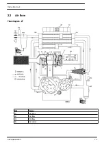
Page 15: ...2 2 Air flow Flow diagram ZT Ref Name 1 Air inlet 2 Air flow 3 Oil flow 4 Air outlet Instruction book APFS998935v00 13 ...

Page 16: ... The cooled air is further compressed in high pressure compressor element Eh and discharged through silencer AS and aftercoolers A check valve CV is provided downstream of the silencer The compressed air leaves the compressor via the air outlet 2 3 Condensate drain system Flow diagram ZT Instruction book 14 APFS998935v00 ...

Page 17: ...in collector 2 A capacitive sensor 3 continuously measures the liquid level As soon as the collector is filled up to a certain level pilot valve 4 is activated and diaphragm 5 opens outlet 6 discharging the condensate When the collector has been emptied the outlet closes quickly without wasting compressed air When the controller registers a malfunction the red alarm LED starts flashing and the ele...

Page 18: ...st Briefly press the TEST button and check that the valve opens for condensate discharge Checking the alarm signal Press the test button for at least 1 minute Check that the alarm LED flashes Release the test button Instruction book 16 APFS998935v00 ...

Page 19: ...2 4 Oil system Flow diagram ZT Explanation of arrows Ref Name 1 Air inlet 2 Air flow 3 Oil flow 4 Air outlet Instruction book APFS998935v00 17 ...

Page 20: ...r Co Then the oil flows through the cooling jackets of compressor elements El and Eh From there the oil flows through filter OF towards the bearings and timing gears Valve BV opens if the oil pressure should rise above a given value 2 5 Cooling system Flow diagram ZT Instruction book 18 APFS998935v00 ...

Page 21: ...le for recovery is between 80 and 95 depending on the operating conditions If an MD dryer is installed downstream of the compressor this percentage is reduced to approx 70 of the shaft input instead of approx 90 as part of the heat in the compressed air is used for regeneration in the drying process A complete energy recovery system includes Compressor with modified cooling system ZR A pump unit P...

Page 22: ...tes the hot cooling water from the compressor through the heat consumer and back to the compressor The other is a stand by pump Check valves CV1 2 at the delivery side of the pumps prevent backflow of water in the stand by pump The pump unit is fitted with a make up water connection an air trap with automatic de aeration device AT a pressure and temperature gauge PI and TI a safety valve SV and an...

Page 23: ...h motor is equipped with manual starting equipment including a circuit breaker The first time it is started check that the rotation direction matches the direction indicated by the arrows on the motor flanges If necessary stop the unit switch off the voltage and reverse two incoming electric lines Important remarks Compressed air quality and reliability of any compressor dryer or other equipment s...

Page 24: ...ystem mainly includes Elektronikon regulator Emergency stop button S2 Electric cabinet Drive motor M1 Pressure and temperature sensors Elektronikon regulator 1 and emergency stop button S2 Electric cabinet Typical example Instruction book 22 APFS998935v00 ...

Page 25: ...Typical example Drive motor M1 Instruction book APFS998935v00 23 ...

Page 26: ...able settings e g the unloading and loading pressures the minimum stop time and the maximum number of motor starts are taken into account The regulator stops the compressor whenever possible to reduce the power consumption and restarts it automatically when the net pressure decreases In case the expected unloading period is too short the compressor is kept running to prevent too short standstill p...

Page 27: ...e will appear on display 1 to warn the operator to carry out the service actions belonging to that level Automatic restart after voltage failure The regulator has a built in function to automatically restart the compressor if the voltage is restored after voltage failure For compressors leaving the factory this function is made inactive If desired the function can be activated Consult the Atlas Co...

Page 28: ...he right can be modified 5 Function keys Keys to control and program the compressor 6 Voltage on LED Indicates that the voltage is switched on 7 General alarm LED Is lit if a shut down warning condition exists or maintenance is required 7 General alarm LED Flashes if a shut down condition exists if an important sensor is out of order or after an emergency stop 8 Automatic operation LED Indicates t...

Page 29: ...reviously shown option or menu Cancel To cancel a programmed setting when programming parameters Delete To delete compressor start stop commands Help To find the Atlas Copco internet address Limits To show limits for a programmable setting Load To load the compressor manually Mainscreen To return from a menu to the main screen Menu Starting from the main screen to have access to the submenus Menu ...

Page 30: ...croll key with the same symbol can be used to see the previous item When the scroll key is kept pressed the scrolling is continued 3 5 Emergency stop button Control panel In case of emergency press button S2 to stop the compressor immediately At the occurrence of an emergency stop the compressor element is stopped immediately and the solenoid valve will be deactivated by Elektronikon regulator No ...

Page 31: ...e voltage to the compressor Close the air outlet valve and open the manual condensate drain valves to depressurize the air system Apply all relevant Safety precautions 3 6 Control programs Description In order to facilitate programming and controlling menu driven control programs have been implemented in the regulator Instruction book APFS998935v00 29 ...

Page 32: ...in short the operation status of the compressor Is the gateway to all functions Status data Calls up the status of the compressor protection functions shut down shut down warning service warning and warning Resets a shut down motor overload and service condition Instruction book 30 APFS998935v00 ...

Page 33: ...mands Configuration time date display language Service Calls up service plans and resets the timers after carrying out the service actions belonging to a plan Saved data Calls up the saved data last shut down last emergency stop data Unload Load Loads and unloads the compressor manually 3 7 Calling up menus Description Control panel When the voltage is switched on the Main screen is shown automati...

Page 34: ...ator Procedure The Main screen is shown automatically when the voltage is switched on If the function or arrow keys 1 2 and 3 are not used for some minutes the regulator will automatically return to the Main screen Whenever displayed on a submenu screen press the Mainscreen F1 key to return to the Main screen Example of Main screen of ZR ZT 55 up to ZR ZT 90 Compressor Outlet 7 5 bar Automatically...

Page 35: ...menu gives information regarding the status of the compressor protection functions shut down shut down warning and service warning and allows resetting of a shut down motor overload and service condition Procedure Starting from the Main screen see Main screen menu Press the key Menu F1 the option Status Data will be followed by a horizontal arrow Press the tabulator key 2 No message exists General...

Page 36: ...remedying and when the shut down condition has disappeared switch on the voltage and press the key Reset F3 Press the keys Menu and Mainscreen to return to the Main screen and restart the compressor by means of start button 3 A shut down warning message exists A shut down warning level is a programmable level below the shut down level If a shut down warning exists LED 1 is alight The Main screen w...

Page 37: ... 2 to select the Status data menu the option Service is blinking Scroll to this option and select it by pressing the tabulator key 2 two options may blink Inputs if the programmed service level of a component is exceeded e g the maximum pressure drop of the air filter Plan if a service plan interval is exceeded Stop the compressor and switch off the voltage In case the service message was referrin...

Page 38: ...ors is linked to a shut down service or warning function both the actually measured value as well as the corresponding shut down warning or service level can be called up by pressing key 2 3 11 Counters menu Control panel Function To call up The running hours The loaded hours The number of motor starts The number of hours the regulator module has been under tension The number of load cycles Proced...

Page 39: ...ey Press arrow down key 1 until Test is followed by a horizontal arrow Activate the menu by pressing the key 2 To perform a display test If necessary scroll through the menu until Display Test is followed by a horizontal arrow Press the key 2 During testing the regulator will generate a series of patterns on the display which enable the operator to check that each pixel still functions normally th...

Page 40: ...edure Starting from the Main screen see Main screen menu Press the key Menu F1 Press the arrow down key 1 until Modify Parameters is followed by a horizontal arrow Activate the menu by pressing the tabulator key 2 The first item Parameters will be followed by a horizontal arrow Press the tabulator key 2 the first items and their settings will appear Press the arrow down key 1 until the parameter t...

Page 41: ...the most important settings 3 15 Modifying protection settings Control panel Function To modify protection settings Shutdown e g for the compressor element outlet temperature Shutdown warning e g for the compressor element outlet temperature Service warning e g for the maximum pressure drop over the air filter To check various compressor conditions e g the status of the emergency stop button Some ...

Page 42: ...ng that the shut down warning value can be modified the procedure is similar to the description above The procedure to modify other items is similar For some settings a delay can be programmed Example of the screen for ZR ZT compressors Element 1 outlet 178 C Shutdown Maximum 235 C Menu Modify F1 F2 F3 The regulator will not accept new values beyond the limits Press the key Limits to check the lim...

Page 43: ...to pressure band 2 On Saturday at 18 00 stopping Starting from the Main screen see Main screen menu Press the key Menu F1 Press the arrow down key 1 until Modify Parameters is followed by a horizontal arrow Activate the menu by pressing tabulator key 2 Use the arrow down key 1 to scroll until the option Clock Function is followed by a horizontal arrow Activate the menu by pressing tabulator key 2 ...

Page 44: ...nd modify this line in a similar way to the following command 06 15 Pressure Band 1 Press the key Menu F1 and scroll to Friday Thursday Friday Saturday Menu Delete F1 F2 F3 Programming the command to change over at 18 o clock to Pressure Band2 is carried out in a similar way as described above Press the key Menu F1 and scroll to Saturday Programming the command 18 00 Compressor Stop is carried out...

Page 45: ...fying a command Suppose the command to stop the compressor on Saturday 18 00 is to be modified i e stopping at 17 o clock instead of 18 o clock Starting from the Main screen press the key Menu F1 press the arrow down key 1 until the option Modify Parameters is followed by a horizontal arrow Activate the menu by pressing the tabulator key 2 Use the arrow down key 1 to scroll until the option Clock ...

Page 46: ...owing screen appears Monday Tuesday Wednesday Menu Delete F1 F2 F3 Scroll through the display until Monday is followed by a horizontal arrow Press the tabulator key 2 Scroll through the compressor start stop pressure band commands until the first empty command line is indicated by the horizontal arrow Press the key Modify the first two digits start blinking Enter 18 00 Compressor Stop using the sc...

Page 47: ... screen appears Clock Function Not Activated Menu Modify Delete F1 F2 F3 Deleting all commands Press the key Delete in the screen above A question to confirm the deleting operation will appear Deleting all commands of a specific day Scroll through the display until the desired day is followed by a horizontal arrow Press the key Delete a question to confirm the deleting operation will appear Deleti...

Page 48: ...y Modify F2 the first field 14 will blink Use the scroll keys 1 to change the setting then press the tabulator key 2 to go to the next field 30 The setting of this field can now be modified using the scroll keys 1 Press the key Program F1 to program the new value or the key Cancel F3 to cancel the modification operation the original value will be retained The procedure to modify other parameters i...

Page 49: ...e Elektronikon regulator When a service plan interval is reached a message will appear on the screen see section Status data After carrying out the service actions related to the indicated levels the timers are to be reset Example Service plans Intervals Service plan A Every 4000 running hours Service plan B Every 8000 running hours Service plan C Every 16000 running hours Service actions accordin...

Page 50: ...s Press the arrow down key 1 to find out which service plans were carried out previously following screen appears Previous Timer Level A 4008 hrs Back F1 F2 F3 The screen shows that plan A was carried out at 4008 running hours Stop the compressor switch off the voltage and carry out the service operations related to the indicated service plans see section Preventive maintenance schedule Switch on ...

Page 51: ...The first option is shown Last shutdown 1 Press the tabulator key 2 to find out the date time and other data reflecting the status of the compressor at the last shut down If desired scroll through the other items 3 21 Programmable settings Parameters Minimum setting Factory setting Maximum setting Motor running time in star sec 10 10 30 Load delay time star delta sec 10 10 30 Number of motor start...

Page 52: ...n warning level F 212 410 428 Compressor element 1 outlet temperature shut down level C 211 220 220 Compressor element 1 outlet temperature shut down level F 412 428 428 Compressor element 2 outlet temperature shut down warning level C 100 210 220 Compressor element 2 outlet temperature shut down warning level F 212 410 428 Compressor element 2 outlet temperature shut down level C 211 220 220 Comp...

Page 53: ...sor element 1 2 Element 1 stands for the low pressure compressor element element 2 stands for the high pressure compressor element The regulator does not accept illogical settings e g if the warning level is programmed at 401 F the minimum limit for the shut down level changes into 402 F The recommended difference between the warning level and shut down level is 18 F Required stop period Minimum s...

Page 54: ...mit for the loading pressure changes into 100 psig The recommended minimum pressure difference between loading and unloading is 9 psig Delay at shut down signal Is the period during which the signal must exist before the compressor is shut down If it should be required to program this setting at another value consult Atlas Copco Instruction book 52 APFS998935v00 ...

Page 55: ...4 Installation 4 1 Dimension drawings Dimension drawing ZT Pack Instruction book APFS998935v00 53 ...

Page 56: ...ucting 8 Automatic drain aftercooler 9 Automatic drain intercooler 10 Compressed air outlet compensator 11 Mass 18 Cooling Full Feature air outlet 19 Cooling Full Feature air inlet 20 If option Prepared for MD 21 Cable box included for EC variants 22 Cable box not included for CSA UL variants 23 Automatic drain regeneration outlet 24 Low load drain optional 25 Automatic drain extra aftercooler Ins...

Page 57: ...4 2 Installation proposals Installation proposal ZT Pack Instruction book APFS998935v00 55 ...

Page 58: ...oling air to the compressor is avoided The air velocity to the grids should be limited to 5 m s 195 in s The required ventilation capacity per compressor installed to limit the compressor room temperature can be calculated as follows On ZT compressors Qv 0 92 N dT Qv required ventilation capacity in m3 s N shaft input of the compressor in kW dT temperature rise over ambient in C If cooling air duc...

Page 59: ...ABLE The cable size is valid at maximum ambient temperature of 40 C The cable size is valid at maximum ambient temperature of 104 F 60Hz IEC Pack compressors 380 V ZT ZR55 3 x 70 35 mm2 4 4 Electric connections Example of electric cabinet Typical example Instruction book APFS998935v00 57 ...

Page 60: ...rolled automatic condensate drains F21 Overload relay drive motor K11 Auxiliary relay loading K21 Line contactor K22 Star contactor K23 Delta contactor Q1 Circuit breaker T1 Main transformer T2 Transformer control circuit 1X0 Power supply terminals 1X4 5 6 7 Terminal strips Instruction book 58 APFS998935v00 ...

Page 61: ...rmistor protection 4 Motor heater 5 Fan motor external dryer Only for ZT compressors 6 Only for ZT 200 230V 7 Only for ZT 380 575V 8 Terminals only for ABB contactor types 145 9 If 3 fuses prescribed 10 If 6 fuses prescribed 11 Warning 12 Shut down 13 Low load heater 14 Temperature sensor low load heater Instruction book APFS998935v00 59 ...

Page 62: ...Ref Name 15 To be installed by the customer 4 5 Pictographs Explanation of pictographs Ref Name 1 Start 2 Scroll keys 3 Tabulator key Instruction book 60 APFS998935v00 ...

Page 63: ...onnecting the compressor electrically consult the Instruction book for the motor rotation direction 14 Torques for steel Fe or brass CuZn bolts 15 Consult the Instruction book before greasing 16 Switch off the voltage before removing the protecting cover inside the electric cabinet 17 Oil the gaskets screw on the filters and tighten by hand approx one half turn 18 Consult the Instruction book befo...

Page 64: ...the frame equally The chains must be held parallel to the bodywork by chain spreaders in order not to damage the compressor The lifting equipment must be placed in such a way that the compressor is lifted perpendicularly Lift gently and avoid twisting 5 2 Initial start up Procedure Consult Electric cables Installation proposals and Dimension drawings A sticker dealing in short with the operation i...

Page 65: ...On ZT compressors remove bolts 1 and supports 2 immobilizing the vibration dampers of the coolers Remove support 3 immobilizing the vibration dampers of the gear casing Instruction book APFS998935v00 63 ...

Page 66: ...lled in the intercooler at the condensate drain receiver side Refit the flange Position of silica gel bags on ZT compressors Check that the gear casing is filled with oil the level should be in the middle of sight glass SG Instruction book 64 APFS998935v00 ...

Page 67: ...ond to the local codes The installation must be earthed and protected by fuses in all phases An isolating switch must be provided Check the connections at the primary sides of transformers T1 and T2 Typical example Instruction book APFS998935v00 65 ...

Page 68: ...f the voltage and reverse two incoming electric lines On ZT compressors remove panel 1 and check the rotation direction of the fan motor If the rotation direction is wrong switch off the voltage and reverse two connections at terminals 221 up to 226 of terminal strip 1X1 Run the compressor for a few minutes and check that it operates normally Stop the compressor If necessary top up the gear casing...

Page 69: ...y all related Safety precautions Procedure Step Action 1 Check the oil level which must be in the middle of sight glass SG Top up if necessary with the correct type of oil Position of oil sight glass on ZT compressors Instruction book APFS998935v00 67 ...

Page 70: ...D 2 lights up 3 Press start button 1 The compressor starts running and automatic operation LED 3 lights up When the compressor is stopped and automatic operation LED 3 is alight the compressor may start automatically If the start stop timer is active the compressor may start automatically even if it was stopped manually Instruction book 68 APFS998935v00 ...

Page 71: ...inks See Elektronikon control system 3 The display will show a service message if a service plan interval has been exceeded or if a service level for a monitored component has been exceeded Carry out the service actions of the indicated plans or replace the component and reset the relevant timer Consult your Atlas Copco Customer Centre See also Preventive maintenance schedule 4 Regularly check the...

Page 72: ...ompressor only use the emergency stop button in case of emergency Step Action 1 Press the test button on top of the electronic water drains while the compressor is running loaded 2 Press stop button 1 the compressor will stop and LED 2 will go out 3 Close the air outlet valve 4 To stop the compressor immediately press emergency stop button S2 5 Close the cooling water inlet valve Instruction book ...

Page 73: ...connect the compressor from the mains 3 Shut off and depressurise the part of the air net which is connected to the outlet valve Disconnect the compressor air outlet pipe from the air net 4 Drain oil and condensate circuits 5 Disconnect the compressor condensate piping from the condensate drain net Instruction book APFS998935v00 71 ...

Page 74: ... and long service life carry out following operations at the interval period or running hours which comes first The longer interval checks must also include the shorter interval checks The local Atlas Copco Customer Centre may overrule the maintenance schedule depending on the environmental and working conditions of the compressor Period Running hours Operation Daily 8 Check readings on display Da...

Page 75: ...r made service agreement It will ensure optimum operational efficiency minimize downtime and reduce the total life cycle costs 6 5 Service plan A number of service operations are grouped called Level A Level B Level C Each level stands for a number of service actions to be carried out at the time intervals programmed in the Elektronikon regulator When reaching a level a message will appear on the ...

Page 76: ...ty and interval for the motor bearings 6 7 Oil specifications Oil type Use Atlas Copco Roto Z oil which has been specially developed for oil free rotary compressors This oil has a long service life and ensures optimum lubrication Never mix oils of different brands or types Atlas Copco Roto Z oil Atlas Copco Roto Z oil can be ordered in following quantities Instruction book 74 APFS998935v00 ...

Page 77: ... 55 18 Us gal drum 45 98 Imp gal drum 7 32 cu ft drum 2908 8500 00 6 8 Storage after installation Run the compressor e g twice a week until warm If the compressor is going to be stored without running from time to time protective measures must be taken Consult Atlas Copco Instruction book APFS998935v00 75 ...

Page 78: ...Step Action 1 Stop the compressor and switch off the voltage to the compressor 2 Remove the filter 3 Fit the new filter 4 After carrying out the service actions of the related service plan the service warning must be reset See also Preventive maintenance schedule Instruction book 76 APFS998935v00 ...

Page 79: ...ed press emergency stop button S2 and switch off the voltage to the compressor 3 Remove filler plug FC Drain the compressor sump by opening drain valve Dmo Close the valve after draining Drain the oil cooler by removing its drain plug and vent plug Drain the oil of the compressor elements Yellow painted drains plugs are provided on both elements Instruction book APFS998935v00 77 ...

Page 80: ...n the compressor for a few minutes Stop the compressor If necessary top up the gear casing with oil to the middle of the sight glass SG 8 After carrying out the maintenance operations of the related service plan the service warning must be reset See also Preventive maintenance schedule 7 3 Safety valves Testing The valves can be tested on a separate compressed air line If a valve does not open at ...

Page 81: ...or recirculation of cooling air Improve ventilation of compressor room and avoid cooling air recirculation Air filter clogged Replace filter Condensate is not discharged from condensate traps during operation Discharge flexible clogged Check and correct as necessary Electronic water drain malfunctioning Consult Atlas Copco LED s of electronic water drain do not light up Compressor is running unloa...

Page 82: ...hen test button is pressed Sensor dirty Clean sensor Air pressure below minimum pressure Increase air pressure EWD continuously discharges air Control air blocked Check and correct as necessary Sensor dirty Clean sensor Instruction book 80 APFS998935v00 ...

Page 83: ...m working pressure bar e See Compressor data 9 2 Settings of safety valves Settings Reference Value Value Low pressure safety valve 3 7 bar e 54 psig High pressure safety valve ZT ZR55 75 7 25 bar 105 psi and ZT ZR 7 5 bar 109 psi 9 3 bar e 135 psig 9 3 Circuit breakers and fuses 60Hz IEC ZT ZR55 Instruction book APFS998935v00 81 ...

Page 84: ...e air humidity 0 Air inlet temperature C 20 Air inlet temperature F 68 Cooling water inlet temperature C 20 Cooling water inlet temperature F 68 9 5 Limitations Limitations Value Value Maximum air inlet temperature 40 C 104 F Minimum air inlet temperature 0 C 32 F 9 6 Compressor data ZT 7 25 bar 60Hz Unit ZT55 Nominal working pressure bar 7 Nominal working pressure psi 101 53 Maximum working press...

Page 85: ...sure ZT Full Feature kW 71 0 Power input at maximum working pressure ZT Full Feature hp 95 21 Oil capacity l 38 Oil capacity Us gal 10 04 Oil capacity Imp gal 8 36 Oil capacity cu ft 1 34 Sound pressure level According to PNEUROP CAGI test code with a tolerance of 3 dB under free field conditions at 1 m distance According to PNEUROP CAGI test code with a tolerance of 3 dB under free field conditio...

Page 86: ...nd fall under the exclusion of article I section 3 6 Parts subject to the Simple Pressure Vessel Directive 87 404 EEC are excluded from 97 23 EC according to article I section 3 3 The following pressure bearing parts are of category higher than I Safety valve Category IV Design code AD Merkblätter A2 Vessel IMD260 Category III Design pressure 11 bar e 159 54 psig content 91 l 24 02 US gal 20 02 Im...

Page 87: ...11 Documentation Declaration of conformity Typical example of a Declaration of Conformity document Instruction book APFS998935v00 85 ...

Page 88: ......

Page 89: ......

Page 90: ...ans having the flexibility to adapt to the diverse demands of the people we cater for It s the commitment to our customers business that drives our effort towards increasing their productivity through better solutions It starts with fully supporting existing products and continuously doing things better but it goes much further creating advances in technology through innovation Not for the sake of...

Reviews: